This thread has been locked.

If you have a related question, please click the "Ask a related question" button in the top right corner. The newly created question will be automatically linked to this question.

LM258: Differential current measurement for SG2524

Part Number: LM258
Other Parts Discussed in Thread: SG2524, , TLV272

Hello,

I'm having some issues with a current measurement on a newly designed PCB. I have a 2.5m current measurement resistor that is to carry a maximum of 20A. It is connected as in figure.

The idea is that when the current reaches 20A, we get a 40mV voltage on the current measurement resistor. Thisis then amplified by a factor 4 by one of the two lm258 in the SOIC8 package. The output is fed to the Current limitation + pin of an SG2524 (pin 4). This shoul limit current at approximately 20A as the threshold for the SG2524 is 200mV.

The lm258 is supplied between 12V and ground.

The issue is that with no current in the current measurement resistors, we get an output voltage of 470mV instead of approximately 0V. This is an issue as it causes the system to not operate as it is always in current limitation. What could be the issue/solution?

Thanks,

Gabriele Ulissi

  • Hello Gabriele,

    Please understand that due to the US holiday, we have multiple team members out of the office on vacation.

    In the meantime, can you please share your TINA simulation with us?

    AT 20A and the 2.5mohm resistor, I expect the shunt voltage to be 20*.0025=50mV. With a gain of 4V/V I expect the output to be 200mV.

    Please understand that the LM258 (depending on grade) has a large offset voltage (multiple mV's) compared to your maximum shunt voltage. Are you performing a 2 point calibration?

    At "0" current, the shunt voltage is likely not actually 0mV. There is not only the offset voltage of the device but also errors such as CMRR. Therefore I recommend measuring the voltage across the shunt and combine it with other errors, multiply that value by the gain, and then see how it compares to the output voltage.

    Finally, the output of the device depends not only on the input, but also the output swing limitations. Here are some resources that discuss current sensing and input/output limitations of op amps. You need to ensure that the node voltages at the inverting and non-inverting inputs of the device are still within the linear operating region.


    e2e.ti.com/.../3478.current-sensing-fundamentals


    www.ti.com/.../precision-labs.html


    Hope this helps!
  • Hi Pete,

    Thanks for your answer. As you correctly point out, even with no current the shunt voltage is not actually 0mV. This and other errors are not an issue as this application does not require current limitation at a precise level.
    Upon further investigation the circuit in the figure that I attatched works as expected when operating autonomously. The problem only arises when connecting the LM258 output to the SG2524 current limiting + pin. I would gladly attatch my TINA files, but unfortunatley there is no SG2524 model available on TINA so we are just working with the PCB and a breadboard.

    For further clarification, our current limitation + pin (4) of the SG2524 is connected directly to the LM258 output, while the current limitation - pin (5) is grounded.

    As far as I understand, both current limitation pins on the SG2524 are inputs to the device, so this behavior is unclear to me.

    Thanks and best regards,

    Gabriele Ulissi
  • Gabriele,

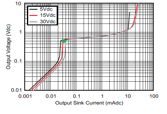
    I suspect that the SG2524 pin provides a significant current (>30uA) that the LM258 output pin attempts to sink to ground (for Vout=0V).

    470mV minimum output is typical on the green dot part of the curve (about 30uA)

    Chart is figure 9 in LM258 data sheet.

  • Gabriele,

    Changing to TLV272 is a solution to this issue.
    A pull down resistor is also an option; 1k will greatly improve VOL.
  • Hi Ron,

    Thanks for your reply. A relatively small pulldown does improve the performance as you suggested.

    Thanks and best regards,

    Gabriele