This thread has been locked.

If you have a related question, please click the "Ask a related question" button in the top right corner. The newly created question will be automatically linked to this question.

Linear Thermoelectric Cooler Driver

Other Parts Discussed in Thread: OPA569, OPA549

Hi ,

I want to design a linear thermo electric cooler driver with analog PID control. The maximum I,V ratings of the module is 5.8A,15.7V.The input supply volatage is not a problem.

I was looking on to the part numbers OPA 549 .Can this IC could both sink and source 8A continuous while running from a single positive supply?I was thinking about using this two of these parts directly to drive a TEC as mentioned in opa569 datasheet

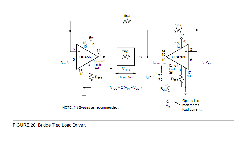
I was also looking on to the "OPTOELECTRONICS CIRCUIT COLLECTION" by By Neil Albaugh of SBEA001 - SEPTEMBER 2001 from TI which has Linear TEC drvies

exapmles for upto 2A using A bridgetied load (BTL) amplifier topology.


Is it possible to extend this circuit to higher currents & voltage ranges by changing the transistors at output?

Can somebody tell me which would be the best topology among above listed?

Regards

Stephen Thomas


  • Hello Stephen,

    Two OPA549 power operational-amplifiers can be employed as a bridge-tied TEC driver powered by a single supply arrangement. Some parameters to consider are the input common-mode range required, the output voltage swing - especially at the higher current drive levels, and the safe operating area (SOA)of the OPA549. Convenient programmable current limiting and thermal shutdown help protect the OPA549 from unsafe operating conditions. You would have to carefully consider the SOA plot shown in data-sheet Figure 6, to determine if two OPA549 devices can provide 15.7V across the TEC while sinking and sourcing 5.8A. A good thermal environment would be required to keep the case temperature within the limits dictated by the SOA curves.

    The alternate circuit diagram that you provided is another approach using a low power operational-amplifier to drive discrete power transistors. It has the potential to provide higher power output than the OPA549 solution, but at the expense of increased circuit complexity. It does appear to have TEC current sensing. Any thermal management would have to be added which further increases circuit complexity.

    Regards, Thomas

    PA - Linear Applications

  • Stephen;

    As the guy who wrote both of those data sheet/application circuits, let me add just a little to what my friend Tom has already said.

    Be wary of substituting other power transistors in place of the ones shown in the app circuit. Those NPN & PNP transistors are nice little surface-mount types made by Zetex; they have a very unique combination of very high Beta together with a high hfe. High beta is necessary since the op amp can only put out a limited amount of current to drive the bases of the power transistors. One might be tempted to substitute Darlingtons since they have very high current gain but Darlingtons have a higher base-emitter voltage and that would limit the output swing on low supply voltages. High frequency cutoff simplifies the loop compensation; slow transistors are harder to stabilize.

    The general principle could be adapted with other higher rated components, of course. Simulating the circuit performance in TINA is easy and helps understand the control loop. I applaud your selecting a linear driver for your TEC. Many people have been lured down the garden path of using a PWM TEC controller, only to find that all they see out of their avalanche photodiode is switching noise.

    Regards, Neil P. Albaugh   ex-Burr-Brown

  • Hi Neil,

    would you recommend substitutions for those NPN & PNP transistors? They seem to be quite exotic ones. Thank you in advance,

    Best regards, Greg 

  • Hello Greg,

    I do not think my former colleague, Neil has been on the forum lately. I tried searching the web for the FTZ869 and FTZ968 bipolar transistors called for in Neil's TEC driver circuit and find nothing other than references to his optoelectronics applications report. The devices appear to be long discontinued.

    Reviewing the schematic and application it appears that they are fast, low voltage, high current transistors.  The TEC bandwidth shown in the application note Fig. 17 extends beyond 10 MHz. Therefore, I expect the fT of these transistors is several hundred Megahertz. Basically, I think these are RF power devices. It may be possible and easier to replace them with fast power MOSFETs operating class AB, instead of class B.

    I will continue searching for information about the transistors and will post anything I find.

    Regards, Thomas

    PA - Linear Applications Engineering

  • Hello Thomas,

    thank you for the help. I figured out that those transistor names are actually misprinted in the schematic: they are FZT869 and FZT968 actually, and now they are running under Diodes Inc. They are not available from our regular sources. However, I'm sure that finding a decent replacement is well beyond my analog knowledge so any help is warmly welcome.

    Best regards, Greg 

  • Hi Greg,

    The Zetex product line of Diodes Incorporated is the only manufacturer for the FZT869 and FZT968 that I find. That may be because these transistors deliver a unique combination of performances that may require a taylored semiconductor process. These transistors develop high HFE at ampere currents levels (300 min. @ 1 A), very low collector-emitter saturation voltage, fT of 100 MHz at low cost. I haven't found any equivalent devices and no one lists a cross reference device for them.

    When I search on line I find that Mouser and Digikey stock these transistors. Certainly other distributors must carry them too.

    Regards, Thomas

    PA - Linear Applications Engineering