This thread has been locked.

If you have a related question, please click the "Ask a related question" button in the top right corner. The newly created question will be automatically linked to this question.

TLV3501: output ripple problem

Part Number: TLV3501
Other Parts Discussed in Thread: TIPD105,

Hi experts,

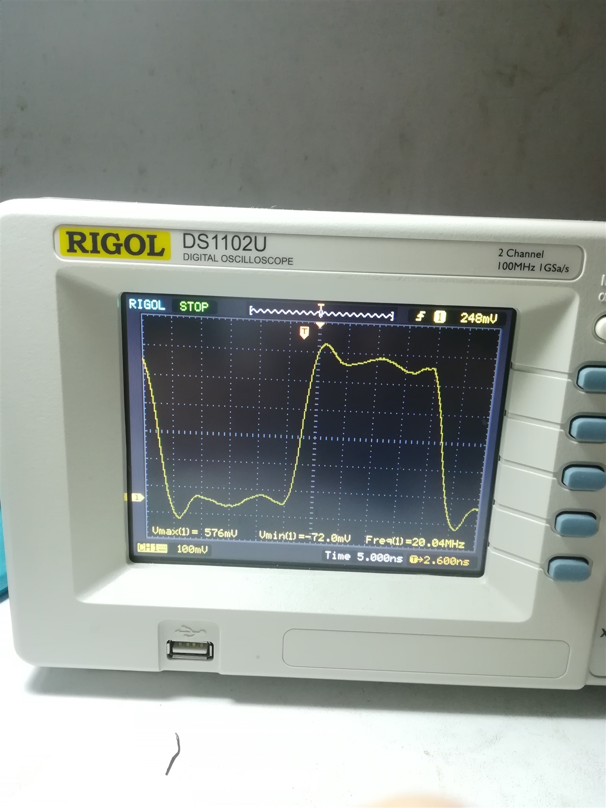
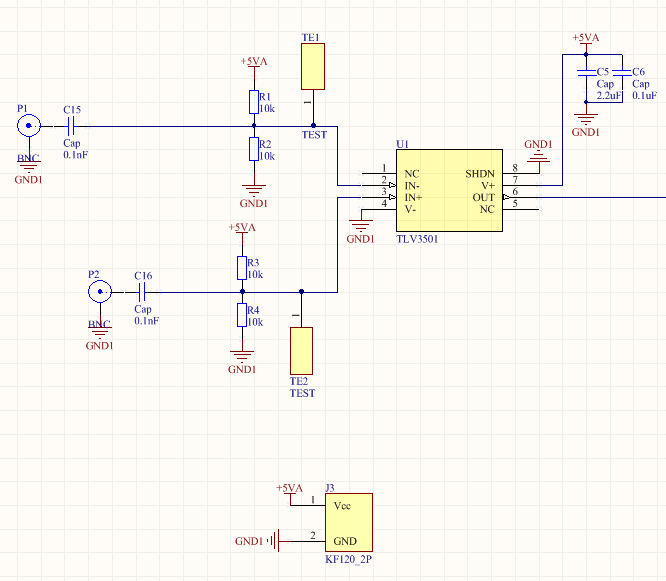
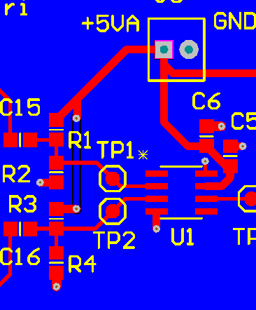
I'm working on TLV3501 circuit now and get one question. The below pics are my circuit schematic, pcb and test waveform, as you could see from the test waveform, there are many ripples this affect my system performance. I get the test waveform using x10 probe. I have already looked some materials related with TLV3501, the TIPD105, it's test result shows that TLV3501 could output 32MHz waveform without any ripple on output. So could you give me some suggestion both on test, schematic and PCB to help get the same test results with TIPD105?

Thanks and Best Regards,

RONDO7174

  • Hi Wei,

    1. If you have a look at the other figures of TIPD105 you will notice that there is ripple, too! Figure 29. i.g. clearly shows ripple.

    2. Even the datasheet of TLV3501 shows ripple. Have a look at figure 9 and figure 10 of datasheet.

    3. Ground wire of scope probe can ruin your measurement in this frequency range. So, you will only see the least ripple if you mount a BNC connector onto the PCB, close to the output pin of TLV3501, and go to the scope with a BNC cable.

    Kai