art Number: OPA551
Hi team,
My customer needs to get the principle. Please check the attach.
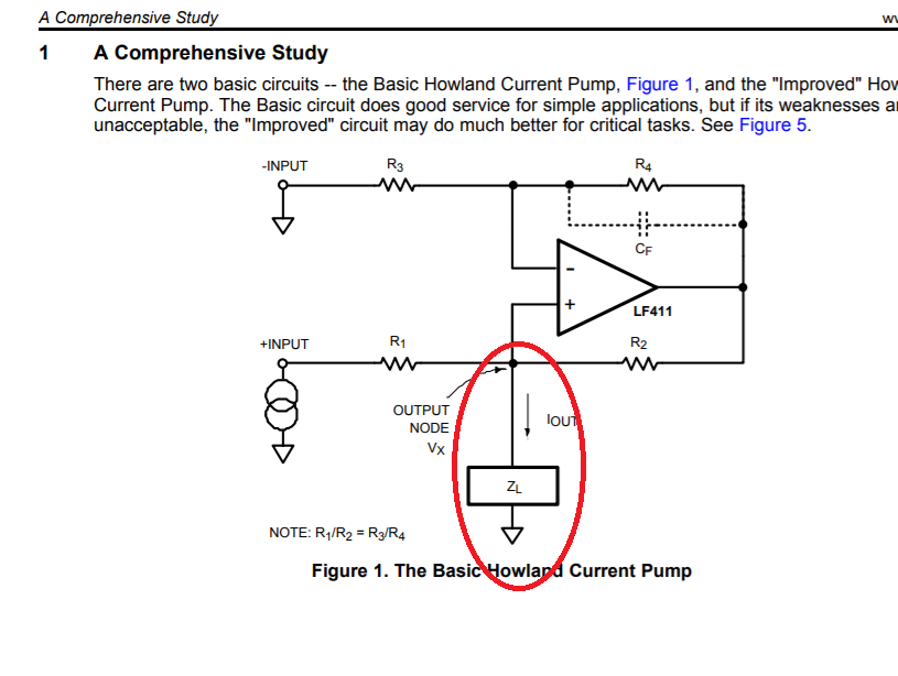
In this pdf, it shows the fiuure1.
Figure 1
And there is a PPT:
1680.Improved Howland Current Pump.ppt
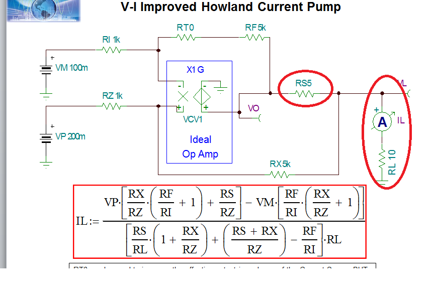
Please check the figure 2
Figure 2
If the figure 1 and figure 2 are both the howland circuit, why the position of RL is different in the
figure 1 and figure 2 ? In the figure 1, RL is connected to R1 and R2. In the figure 2,
RL is connected to the output of the amp and the circuit add RS5.
Would you explain this?


