This thread has been locked.

If you have a related question, please click the "Ask a related question" button in the top right corner. The newly created question will be automatically linked to this question.

LM358A: Oscillating issue for LM358A

Expert 2385 points
Part Number: LM358A
Other Parts Discussed in Thread: LM358

Hi Ti,

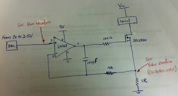
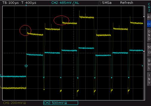
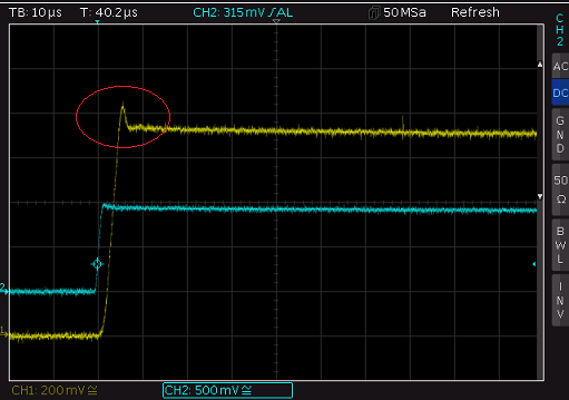
Currently facing some issues with the LM358A oscillation.  Can you share with me how to filter out or reduce this oscillation from below schematic. The waveform also provided for your further reference. Please help to advise.

  • Incognito,

    This could either be a frequency compensation issue or a output current switch time delay issue.
    Let's start with delay factor, try adding a 2k resistor from pin 1 to ground. This will keep the op-amp sourcing current during the steps.
    If this works then see if you can use a higher resistor value if you need to use less system current in the extra component.

    For frequency compensation, it is hard to know the offending frequency because the ringing waveform is saw tooth shaped.
    First try bigger C1, there is no maximum limit other than forward gain bandwidth becoming less.
  • Thanks Ron,

    I would like to confirm the below suggestion from you.

    "Let's start with delay factor, try adding a 2k resistor from pin 1 to ground."

    The above information, 2K resistor adding from op-amp pin 1 to ground is it add a 2K resistor before the 100pF capacitor? 


    "First try bigger C1, there is no maximum limit other than forward gain bandwidth becoming less." 

    The C1 you mention here is it a 100pF cap?

    Previously tried to adjust the C1 from 30pF to 680pF and tested with the above attached picture I get a better waveform when C1 is 95pF to 100pF. 

    I also trying around with two resistor above (100ohm & 10Kohm). The oscillation result that I can obtain is the above resistor and capacitor value combination (the previous waveform attached). 

    Do I still need to increase the C1 value to try on? 

  • It doesn't matter which side of the 100 ohm resistor that the 2k resistor (to ground) is placed.
    Can you add the op-amp output waveform?
  • Hi Ronald,

    Thanks for your suggestion the waveform is stable by adding 2K resistor at Op-amp output (Pin 1, before the 100pF cap) to Ground. Currently faced on different voltage changes there will have a small peak at the initial waveform (see the red circle). Time division: 100us

    After zooming in to 10us time division as picture below shown, there are a small peak at the initial waveform (see the red circle): 


    I'm trying to adjust the resistors values but it doesn't helps at all.  Will there any method to filter out this small peak? Is this is a typical characteristic of this op-amp and can it be ignored?

  • Incognito,

    This is a small overshoot that is a result of the fast rise of the input signal. The LM358A output can not rise that fast due to slew rate limitation. The overshoot is the recovery out of slew rate limit.

    I do not see any issue with this small overshoot, I would ignore it.

    Trying to fix it would round the output edges too much and hurt response time. 

  • Hi Ron,

    Referring to your previous statement "either be a frequency compensation issue or a output current switch time delay issue".

    Can you share with me whether any available application notes or technical notes which have details on explaining this issue? Why is there a reason of adding the 2K resistor from pin 1 to ground and why is the value 2K? What are the roles of the capacitor and other resistors in this circuit?
  • Incognito,

    Attached are the clearly visible in the schematic, but often not comprehended facts about LM358.

    TS321,LM358,LM324_Tech_day.pdf

  • Incognito,

    100 resistor limits gate current on edges and sets the gate rise and fall time.
    1 ohm resistor set current gain, IOUT = VIN / R
    10k and 1nF, closes the loop for DC and provides a high frequency signal path bypass for better phase margin. Full loop through NMOS has more phase lag; bypass from output has less lag. The bypass frequency is 1/(6.28*R*C)