This thread has been locked.

If you have a related question, please click the "Ask a related question" button in the top right corner. The newly created question will be automatically linked to this question.

LMC6482: Unable to get 700mA constant current

Part Number: LMC6482
Other Parts Discussed in Thread: OPA564, OPA541, TINA-TI

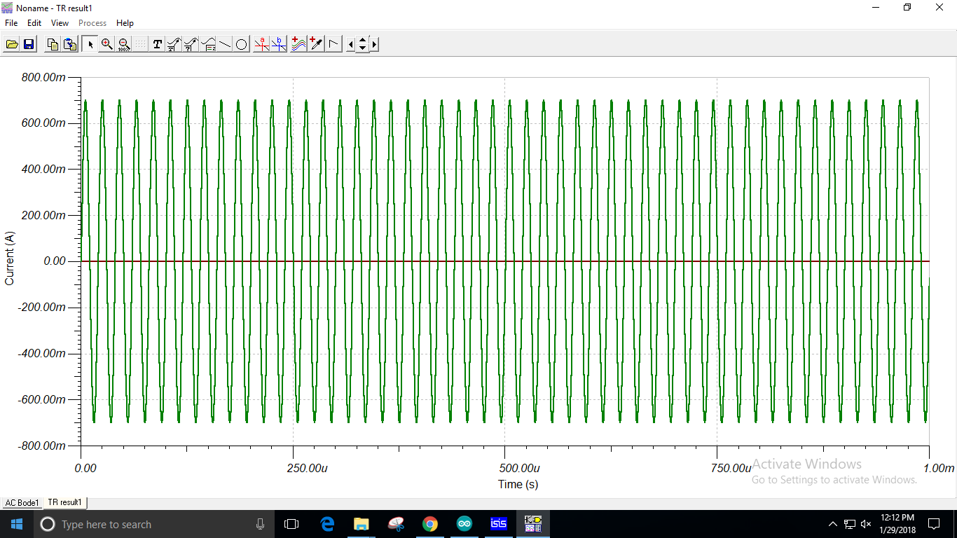
Hi, I'm designing a Bio-Impedance Analyzer for which I need a current of 700mA at 50kHz and 100kHz. I have implemented the Howland current source using LMC6482, but I'm unable to get a constant current at the output. Is there a resistance combination that can get the desired value or is there any other issue? 
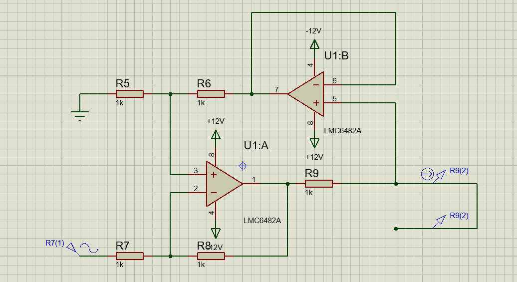
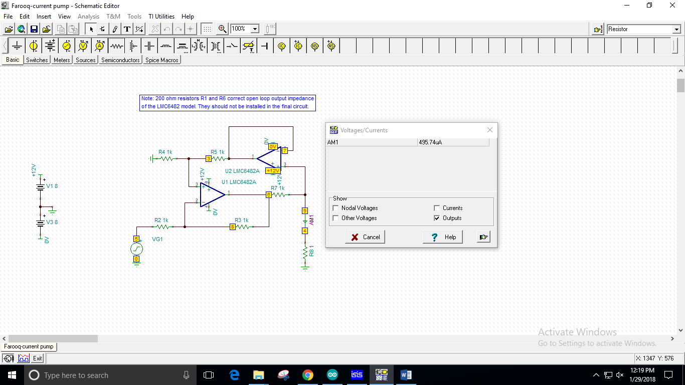
This is my circuit 


  • Hi Roha,
    The LMC6482 specifies a maximum output current of around 30mA, which will fall far short of your desired 700mA. For a 700mA output, you may need a power op amp such as OPA541, OPA564, or a similar part capable of sourcing 700mA continuously.

    Additionally, you will experience problems with the circuit as drawn, as 700mA must flow through the 1kΩ resistance of R9. This would require U1A's output to swing to at least 700V (700V/1000Ω = 700mA).

    Using a 12V supply, as shown, I'd recommend R9 to be 1Ω at most. This would produce a 700mV drop across the resistor, and dissipate 1/2 watt, which is reasonable.

    With this configuration, your output current in Amps would be equal to your input voltage in Volts. If you wanted additional gain, you could increase R6/R8 to do so.
  • I'm really sorry, the current specification was 700uA. This can be handled by the same op-amp?

  • Ah, 700uA should be well within the capabilities of the LMC6482. One thing to note is that the LMC6482 supports a maximum 16V supply, or ±8V, so the ±12V supplies in your schematic will exceed the maximum there. A DC simulation of your circuit in TINA seems to give a 700uA output into a 1kΩ load with a -0.7V input.
  • Even with the voltage adjustment I'm not getting a constant current, the current is in 10^-12-10^-13 range.

    Also does the amplitude if input sine wave affect the output current. We are using 2 sine waves of 20kHz and 100kHz. W e did not face any problems in the DC circuit but AC is proving to be more tricky after each step.

    I'm getting the following output.

  • Hi Roha,

    My apologies for not replying to this sooner. I think the issue may be that there's no return path to ground for the output of your current source in your simulation. Using the attached TINA-TI simulation, I do see a ±700µA current waveform out at 50kHz. AC sweeps indicate that the bandwidth of this circuit is around 400kHz.

    TINA Simulation File

  • Hello Alex,

    The current showing at AM1 is less than 700uA (i.e. 495.7uA). Also when we continue the circuit forward,the currents drop down to pA's.

    1.Exactly where do I have to take the current output so that it remains constant at 700uA.

    2.Also when I plot the current, the current scale shows a value of 700mA. 

    1. 

    2. 

  • I'm sorry, for the second part I was plotting the output, that issue is resolved.
  • Both the issues are resolved.
    Thanks a lot Alex, your answers were a huge help.