This thread has been locked.

If you have a related question, please click the "Ask a related question" button in the top right corner. The newly created question will be automatically linked to this question.

TINA/Spice/LMP7701: Voltage control current source overshoot

Part Number: LMP7701
Other Parts Discussed in Thread: TINA-TI, OPA320, LMP7702,

Tool/software: TINA-TI or Spice Models

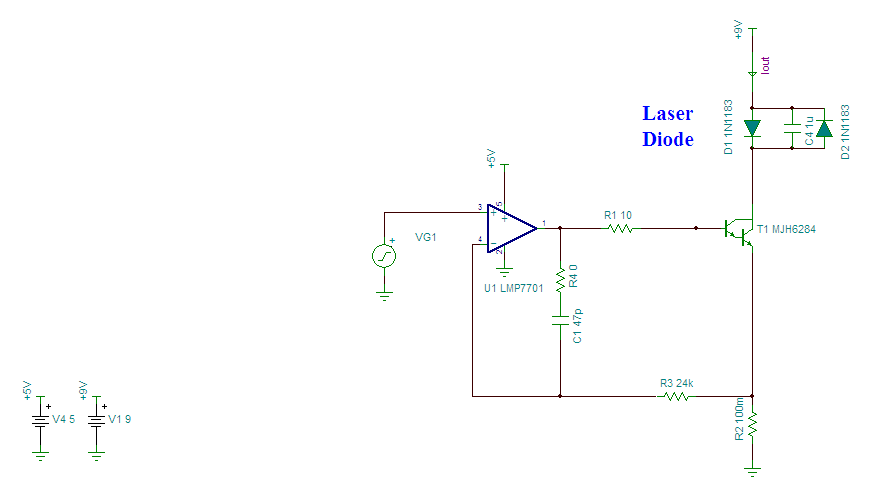
I am making a voltage control current source with LMP7701 opamp and MJH6284 darlington pair transistor. I want to drive a current of 10 A peak to peak @ 100 KHz and 1 A offset. I have overshoot on my current pulse, I checked the phase margin by braking loop ~89 deg noted. I don't understand why I have overshoot even with this good phase margin. I have attached circuit I used for checking the stability and with actual circuit for reference. Stebility_10A driver_09-jan-18V2.TSCmain_10A driver_10-jan-18V2.TSCLMP7702.TSMlmp7701.libOPA320.TSM

  • Hi Ikram,

    I believe that the reason you see such good phase margin is that your loop is not broken correctly. As drawn, your break isolates the op amp's output from the rest of the circuit, so you'll only see unloaded Aol, not loaded Aol. Breaking the loop in the feedback path instead gives a simulated 40°-50° phase margin.

    TINA-TI simulation

  • Thanks Mr.Davis, It was my mistake.

    So, I have ~40 ° margin.  In my system I have two poles at 2.3 Hz (Opamp dominate pole) and 1.42 MHz (system pole*). I am thinking of two option,  first one is to reduce the gain of opamp some how to bring 0 dB point inside and which increase phase margin or add a zero before second pole by adding C_f capacitor. Can you suggest appropriate compensation suitable for my configuration.

  • Hi Ikram,
    We're taking a look at how to stabilize this, but it's a little tricky. Some techniques we've tried, like adding a feedback capacitor, do increase phase margin, but there's still some overshoot due to the fact that this isn't truly a second-order system.
  • Dear Davis,

    I managed to get phase margin to 70 degree by adding a gain stage of 16 V/V. But when I checked my transient response its heavily oscillating. I read about lead lag compensation form TI notes"AN-1604 Decompensated Operational Amplifiers " . But adding this to my circuit have no effect.Please suggest what will be my possible solution.

  • Hi Ikram,

    A couple thoughts:

    1. Try your stability simulation at both your minimum and maximum setpoints. Since the system will move between those two states, if one is unstable, it could result in the whole system appearing unstable.
    2. It's possible that performance may be limited by the output swing of U2.

    I spent a little time playing around with this, and I think the following may work with a little bit of tuning for your exact laser diode: 

    By tweaking the values of C1 and R3, I can get a reasonably flat waveform out during a transient simulation. There is still some residual overshoot, but it's pretty minimal. 

    TINA-TI simulation

  • Hello Davis,

    First, thank you very much for support, I am getting very nice critically damped settling at max current as below. I will use a  variable cap to adjust on PCB. 

    In your last attachment .TSC the phase margin is tuned to ~71 deg by giving lag lead compensation between +IN and -IN , but in working circuit pic in last attachment  its between output and input, when I checked its phase margin (PM) ~61 deg. I would like to know how it translate in transfer function poles and zeros. Intuitively from Ao/B you have added a zero at ~10 KHz . I would like to know calculation part of it, so that I can learn and do this my self next time or some reference will be helpful. Again thank you very much for the support. Further on this, I am working on increasing the switching frequency. 

    for lower currents like 500 mA it was having little overshoot. Then I tried adding lag lead compensation at input side ( +IN and -IN). I noticed performance was consistent between lower and higher current (critically damped system). The values used are R=2.5 K and C=47 nf.

  • Hi Ikram,

    I actually didn't calculate the capacitance value. My tuning process was more iterative, starting with an initial guess of 10pF I saw an underdamped response, but 100pF gave an overdamped response. That bounded the possible capacitance values, so I began searching between those two points to achieve the desired transient waveform, using standard capacitance values to narrow the options down. 47pF appeared to give the desired response, and re-running the AC stability analysis didn't show any issues with the solution.

    Perhaps not the most elegant process, but certainly functional.