This thread has been locked.

If you have a related question, please click the "Ask a related question" button in the top right corner. The newly created question will be automatically linked to this question.

Why is this differential MFB lowpass filter oscillating?

Other Parts Discussed in Thread: LMH6551, TINA-TI

I haven not been using differential amplifiers a lot and I bumped into this problem.

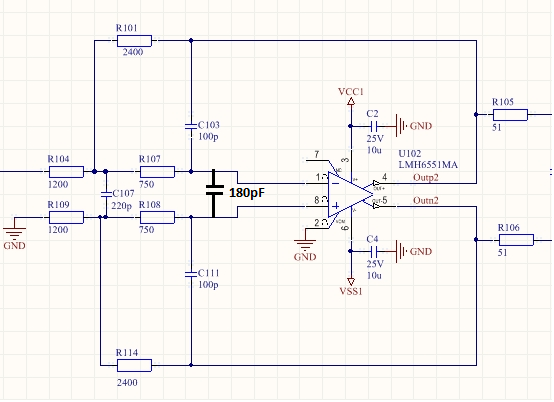
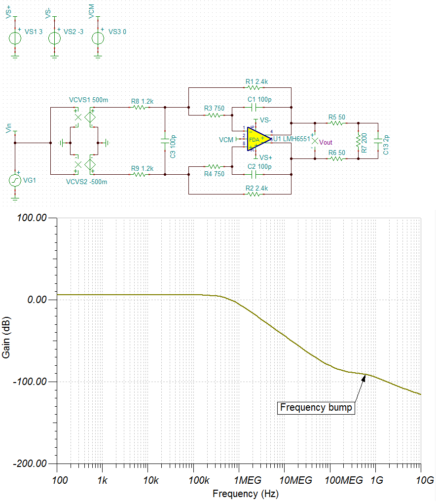
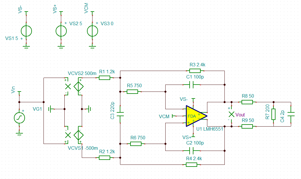
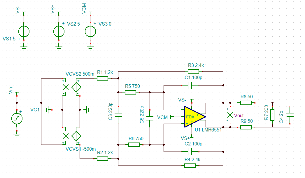
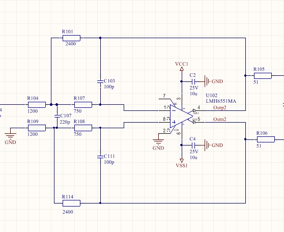
I have calculated this LPF with filter pro and when I build it on the PCB, this filter keeps oscillating until I add a capacitor C125)  after the 51 ohm resistors R105, R106.

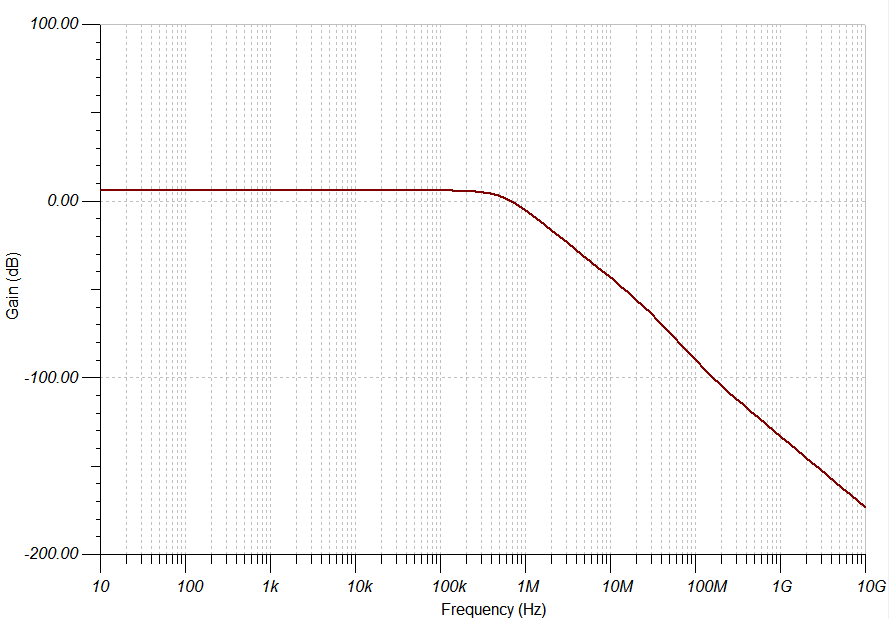
It ocillates  at about 180 MHz even when I have both inputs open. The tracks to the connector are only 3 cm longand differentially routed wth equal length.

I tried this circuit with a GND plane just below the top layer to provide a solid GND and I tried a layout where I gave the GND on a layer more away from the toplayer. like shown here in the images. As can be seen I kept the circuit as symmtrical as I could and avoided GND inderneath the input pins of the IC
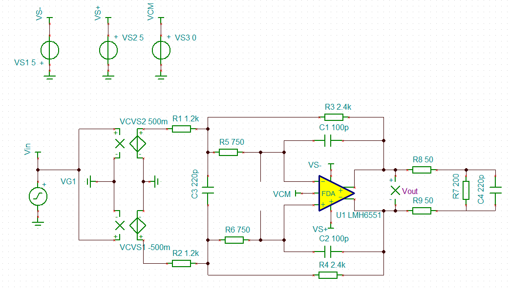
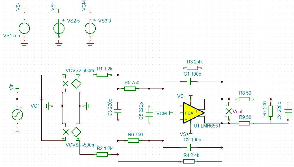
Schematic 

Top layer

Inner layer

Bottom layer

  • Hi Bert,

    Would it be possible for you to add an input capacitor of 180pF or 220pF as shown below across the LMH6551, and see if the oscillations go away? By adding a shunt cap across the inputs, you are essentially increasing the noise gain at higher frequencies and making the amplifier more stable.

    The LMH6551 does tend to oscillate if used in MFB filter configuration and appropriate external noise gain shaping is not employed. You could read about this here where I have verified fix for LMH6551 MFB filter on the bench:

    Best Regards,

    Rohit

  • Hi Rohit,

    I tried adding that capacitor and with 100pF it was still oscillating but with a smaller amplitude.

    With 220pF is is quiet, but how do I determine the proper value? 

    How could I analyze this with Pspice?  

    In my simulation I did not see anything indicating instability.

    Greets

  • Hi Bert,

    I think 180pF to 220pF input cap is about right to stabilize the LMH6551 MFB circuit.  

    I don't think you can directly view the instability on the TINA-TI simulation, but if you simulate your circuit to a higher frequency you do see bump in gain response across frequency which I think is where the instability is. The other thing is that the open-loop frequency response of LMH6551 is not correctly modeled in TINA-TI, which makes it difficult to predict the second order effects at high frequency affecting stability of the circuit.

    However, the underlying principle of adding the input capacitor is to increase the Noise Gain (given by NG = 1+ Cg/Cf) at high frequencies, such that the Noise Gain curve and open loop gain curve of the device intersect at -20dB/decade. I would recommend you to go over the TI Precision labs training that talks about the FDA stability, and it should give a better idea of compensating the FDA for any instability.

    LMH6551 TINA-TI schematic attached: LMH6551_StableMFBFilter.TSC

    Best Regards,

    Rohit

  • Hi Rohit,

    Thanks for your reply. I checked this video And I wil watch it again laer

    I simulated the circuit in Altium spice and in Tina with same result (as expected)

    I included the experiments I have done with tina

    Circuit of the (180 MHz oscillating) filter


    Oscillating at 180 MHz


    Circuit wit 220pF added between + and – inputs od the FDA


    This does not oscillate but has a bump near oscillating frequency


    Circuit with 220pF at the output of the FDA

    This circuit is also not ocsillating


    With 220pF added between + and – inputs od the FDA and 220pF at the output


    This circuit is not oscilating

    With 2.2nF added between + and – inputs od the FDA and 220pF at the output

    This circuit is also not oscillating

     Here there is no bumb in the slope but This is with about 10 times the value suggestd.

    So I am a bit confused.

    Greets,

    Bert

  • But if I want to do a stability analysis
    Would this circuit simulation work?

    Where I use (OutP2-OutN2) to analyze the loop?

  • Hi Bert,

    For stability analysis of your circuit, you need to perform loop gain analysis in-order to determine whether your circuit is stable or not. The LMH6551 device is a voltage feedback amplifier whose closed loop transfer function is given by Acl = Aol/[1+(Aol/NG)], where Aol is the open loop gain and NG is the Noise Gain or 1/feedback factor (Vfb). Stability of your circuit will be determined by the loop gain or Aol/NG term in the denominator, which essentially means intersection of open loop gain with the Noise Gain curve in AC response.

    Now coming to the problem of not significant peaking in the frequency response indicating instability with no input cap, I think that is primarily because the open loop gain curve in TINA-TI for the LMH6551 model is not correct. The TINA-TI model shows Aol curve rolling off at -20-dB/decade beyond 0-dB and exhibiting a right hand plane zero (RHZ) at much higher frequencies, but in reality this RHZ occurs sooner at NG = 3V/V and f = 400MHz with an increased phase shift beyond it (shown by red line for Real Aol model below). I think that the LMH6551 is only stable for NG > or equal to 2V/V (or 6-dB), instead of the NG = -15dB as shown in the TINA-TI model. So, I am checking with the modeling team on this to update the LMH6551 TINA-TI model.

    If we do a Noise Gain (1/Vfb) profile across different input caps intersecting the Real Aol curve,

    1. For no input cap (see plot below), the high frequency noise gain of (1+Cg/Cf) is essentially 1 or 0-dB because the Cg is very low. So, the intersection of NG with the real Aol curve happens in region where the phase shift is already beyond 180' - thus indicating instability. I don't think the LMH6551 TINA-TI model correctly represents the real Aol curve, or else it would have shown peaking in the frequency response.

    2. For 100pF input cap, the high frequency noise gain will be (1+Cg/Cf) or (1+200pF/100pF) or 3V/V. The intersection of NG with the real Aol curve happens where the device is marginally stable, and in some scenarios depending upon the external board parasitic and process variation there is a possibility for the device to oscillate the way you are reporting.

    3. For 220pF input cap, the high frequency noise gain will be 1+440pF/10 u0pF or 5.4V/V. The intersection of NG with the real Aol curve occurs in -20dB/decade region of the Aol where the device is stable indicating low phase shift and phase margin > 60'.

    4. For 2.2nF input cap, the NG intersection with the Aol curve happens at high gains of -20dB/decade indicating a very stable or over damped frequency response. So, increasing the input cap from 220pF to higher value should make the circuit more stable. One caveat though of significantly increasing the input cap is the early roll off in closed loop BW, which is usually not desirable.

    Based on the below analysis, I think the optimal value of input cap to stabilize your circuit is 220pF or if you want more margin then increase it to 270pF.

    I believe this should explain on the usage of input cap for the MFB circuit using the LMH6551, and I apologize for the LMH6551 TINA-TI Aol model to be not representative of the actual device implementation in real world. I am checking with the modeling team on this to update the LMH6551 TINA-TI model.

    Also, the below circuit can be used for stability analysis of an FDA in MFB filter configuration.

    Best Regards,

    Rohit

  • Hi Rohit,

    Thanks for that explanation although it is not all clear to me and I try to understad it completely:)

    I tried to playback your simulation.and probably due to my lack of experience with tina I could not get  the 1/VFB curve. I only het the Vfb curve. 
    How do you calculate on the meter outputs?

    Maybe you could show the acompanying phase plots with the bode plot and indicate why the circuit is oscilating at around 200MHz ? And why that stopne with the extra 220pF cap?

    I understand and see the circuit is stable with that 220pF  And I see the NG going up with adding that 220pF

    Greets,

    Bert

  • Hi Bert,

    Sorry for the delay in reply.

    For the 1/VFB curve calculation in TINA-TI, you run an AC simulation and then use the post-processor tool in plotting graph to make this calculation. The same can be done for Aol calculation of Vout/Vfb.

    As I mentioned earlier, there are inaccuracies in the existing LMH6551 TINA-TI model available on the web which does not let us completely analyze the stability of the MFB circuit at high frequencies. I am working with the modeling team to fix this issue. However, I have plotted the phase shift you should get by using each input cap in real device or model, represented by the light red curve at higher frequencies, and the respective phase margin associated with each of the caps.

    Usually for a right hand plane zero (RHZ) at high frequency, you end up with +20dB/decade correction in the open loop gain curve that flattens the gain response. Butt, the phase starts shifting at -90', which is what hurts in stability of the device at 0-dB Noise Gain. As you can see from the below bode plot curve, the phase has already shifted by more than 90' at 0-dB Noise Gain resulting in instability. However, for 220pF input cap, the phase margin is still at 73' resulting in a stable circuit.

    Best Regards,

    Rohit