This thread has been locked.

If you have a related question, please click the "Ask a related question" button in the top right corner. The newly created question will be automatically linked to this question.

LMH6553: Gain consideration

Guru 16770 points
Part Number: LMH6553

Hi

I have question for gain setting with clamp operation.

According to the description of clamp operation in datasheet P.22, Figure 59 shows example circuit whose gain is 2V/V.

However, I could not find the wave which is represented in gain with 2V/V in the Figure.

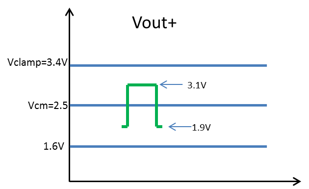
If the output is not clamped for single-ended input in the circuit offering 2V/V gain, how is output level of VOUT+ and VOUT- respectively?

For example, if Vin = 0.5Vpp is assumed in Figure 59, how are VOUT+ and VOUT-?

BestRegards

  • Hi,

    For Figure 59, the input is 2Vpp and with 2V/V gain, each output Vout+ and Vout- should ideally swing 2Vpp represented by the sine wave in the figure above at each outputs. But, because each output is clamped at 2V and 1V on the high and low end respectively due to the Vclamp = 2V, the swing will be limited to 1Vpp at each output. So, the total differential output will be limited to 2Vpp (middle clipped wave on the output) instead of the total differential output being at 4Vpp (2Vpp input*2V/V gain). I don't really understand what you mean by the wave that represents 2V/V gain, because the gain is fixed and not changing like a wave.

    The Vout+ and Vout- output is clamped as you can see for 2Vpp input and 2V/V gain (top and bottom voltage levels).

    If Vin = 0.5Vpp is assumed in Figure 59, each of the Vout+ and Vout- will swing 0.5Vpp from mid rail or Vcm = 1.5V and will be unclamped or not clipped.

    Best Regards,
    Rohit
  • Hi Rohit

    >I don't really understand what you mean by the wave that represents 2V/V gain,

    > because the gain is fixed and not changing like a wave.

    Sorry, my explanation was not clear and I was misunderstanding.

    I had thought SE unclamped output would be double of SE input because gain is 2V/V under unclamped condition.

    The red wave in following figure was my idea.  Of course, I didn't think this would be output, due to output swing limit.

    Anyway, I now understand that each output Vout+ and Vout- should ideally swing 2Vpp if the input is 2Vpp and 2V/V gain.

    Next, let me ask you questions using following circuit.  It is 5V single supply and it has gain of 8.29.

    1.

    At first, I want to confirm if following understanding is correct.

    Supposing SE input and output, VOUT+ or VOUT- would have gain of 4.14 from previous consideration.

    If 0.3Vpp pulse input is supposed, Vout+ should swing 1.2Vpp from Vcm=2.5V and it would be unclamped.

    Is it correct?

    2.

    Next, I obtained actual data like following.

    According to this data, pulse width seems to extend at output if amplitude of input pulse is over 250mV.

    Could it be correct behavior of this IC?

    I appreciate if you could reply.

    BestRegards

  • Hi,

    To answer your questions,
    1. I believe the understanding is correct with each output at 1.2Vpp for 0.3Vpp input, and yes it would be unclamped.
    2. It is possible that the pulse width extension for input amplitudes beyond 250mV is due to the device itself. However, would it be possible for you to set the Vclamp voltage at 3.7V or higher, and check to see if it the clamping operation indeed is responsible for this? Setting the Vclamp voltage at 3.7V should ideally remove clamping operation of the device and operate the device outputs at maximum swing. To be honest, I would not expect the pulse width to change so much even before the signal reaches the clamping voltage.
    Another thing you can try is to increase the device supply voltage, and subsequently the Vclamp voltage, to see if it makes any difference in the pulse width. Also, what is the rise/fall time of the pulse width you are using?

    Best Regards,
    Rohit
  • Hi Rohit

    Thank you for your reply.

    I will check it you pointed out.

    And I answer your question.

    >what is the rise/fall time of the pulse width you are using?
    It is about 5nsec. So the wave is almost like Trapezoid.
    The pulse width is measured at middle of amplitude.

    BestRegards
  • Hi

    Sorry, we must check other issue and the reply for result will be delay a little.

    BestRegards