This thread has been locked.

If you have a related question, please click the "Ask a related question" button in the top right corner. The newly created question will be automatically linked to this question.

LM339: Older devices work, newer devices do not work.

Part Number: LM339

I am using an LM339 in conjunction with a 4401 transistor to control a FET.

I have started to see a rash of FET failures and have been able to make the circuit work and/or fail by changing the LM339.

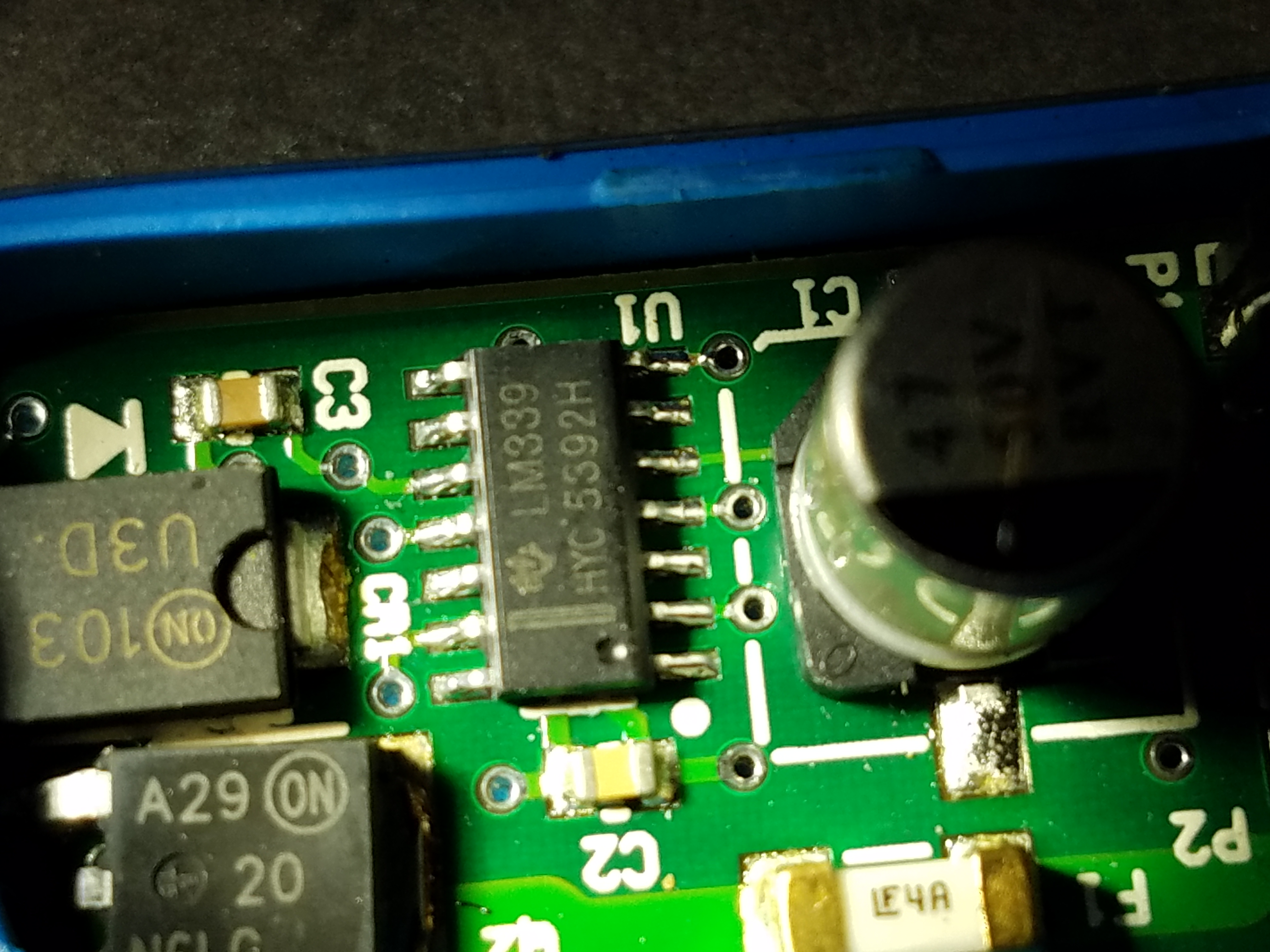
The part markings on all the sample assemblies that fail are 'TI LM339' and  'HYC5392H'.

The markings on the sample assemblies that work are a mixture:

LM339 G4 and 9CADSVM

LM339 and 16P18NAG4

LM339 and 05P042AG3

LM339 G4 and 04ALFDM

What has changed?

  • Hi Brian,

    Can you provide the exact part number you are ordering (Assuming LM339D or PW).

    Can you also provide a schematic that shows both the input signal source and output loads? What is the FET driving?

  • My parts list calls out LM339D.

    I inserted a pdf of the schematic, but I don't think it worked properly. If not is there a convenient way to send you a pdf?

    Inputs:

    P1-1: 24v

    P1-2: Analog input creates xx% duty cycle at FET (above 9v = 100%, below 1v = 0%)

    P1-3: Ground

    Failing output is connected to a solenoid.

    KC_A10732_00_Schematic_CDM.pdf

  • Hello Brian,

    The schematic attached. I see it.

    I have asked the Quality Engineer to look into the date codes and lots to see if there are any differences.

    Is just the LM339 damaged? Or also Q4 or Q2? When the output does fail, does it fail open, shorted or somewhere in between? Is there physical damage (smoke?)? Does the IC get hot?

    Whenever we see a solenoid, we immediately think transient and inductive kick-back issues. These issues are very layout dependent and the layout subtleties are lost in simple schematics. CR1 needs to be right across the connections to the solenoid as they enter onto the board. You do not want to share any circuit traces with the solenoid transient currents. This also includes the ground end of the FET. How big is the solenoid (current-wise)?.

    I would get a scope and look at both P2-1 and P2-2 referred to ground and watch for high voltage transients - particularly when DE-energizing the solenoid - when the reverse voltages are created. Look at the MOSFET source and +24V supply nodes. You also have a fairly small value cap across the solenoid, which can cause it it "resonate" with the solenoid inductance.
  • Hi Brian,

    Can you send a picture of the top and bottom of one of the "bad" device packages? Any maybe a picture of the label on their reel or box?

    The "Bad" units datecode does not make sense. The first two digits are the year and month, which should only run 0-9 and 0-9 & A-C. The last "H" digit also does not make sense.

    The "good" device datecodes seem correct.

    Where did you purchase the 'bad' devices? Do the markings on the "bad' devices look like the "good" devices? Same color/style font? Crooked?
  • The LM339 does not get damaged. Q2 overheats and fails (open). We can monitor and see the temperatures start to rise and shut down before failure occurs. We use this method to stop running before failure and then change the LM339. We can make a good assembly fail, and a failing assembly good, by swapping the LM339.
    These assemblies are built for us by Global Point in China, getting pic's of the reel may be difficult.
    Picture of top of failing LM339, blow-up of TI Logo, and bottom of IC attached.

  • Hello Brian,

    We are very suspicious about the "bad" unit. We would like you to send it in for analysis.

    At this time I would like to take the good/bad portion of the thread conversation privately due to possibly sensitive information. Would it be okay for me to contact you at your email address?

    As for the failure mode: For Q2 to get hot, it would have to be running in the "linear" region (not quite on or off).

    Q2's VGSon max is 4V, so with 12V Q2 should be fully "on".

    The only way I see it not being fully "on" is two ways:

    1. The comparator is oscillating - rapidly turning on-and-off at high frequency (PWM'ing).
    2. U1 output is saturating at around 700mV, which could allow Q4 run in a linear mode (not saturated).

    It can also be a combination of the two...

    You have the hysteresis feedback resistor R5 connected to the negative input. I assume you did this because of the MOSFET output "inversion".

    However, Q4 also adds an inversion, so the "output" at the Q2 source is actually in phase with the comparator output. U1 goes low, pinches off Q4 and turns it "off", then the gate voltage rises to 12V, making the MOSFET conduct and the source goes near 0V.

    So what you have is actually negative feedback. If you add an integration capacitor (or delay), you can have the entire loop go linear.

    Also, you have a capacitor (C3) on the inverting node, which would cause oscillations in a op-amp loop.

    Even if the feedback resistor went to the positive node, the capacitor would negate the positive feedback by adding a delay in the feedback. This softens the fast "snap" required for the positive feedback. What you would see is a noise "burst" until the capacitor charged up. I would remove C3.

    For testing, I would remove R5 and C3 and see if the overheat issue still occurs, and monitor the output votlage of pin 13, and the Q2 gate voltage (with both a scope and DMM).
  • It is OK to contact me directly via my email.

    You have come to the same conclusions that we have. The "bad" LM339 is causing the FET to switch many times each time it should switch once. I can make the changes and tests you suggest, but we get the same results removing these parts would give by setting the input above 9v. At this input, the LM339 sees only one transition on its inputs so the FET comes on and stays on. In this configuration (as long as the load is small enough for the FET to run 100% duty cycle) the boards will run OK.

  • Hi Brian,

    I will contact you directly.

  • Thanks for all your help, Paul.