Hi,
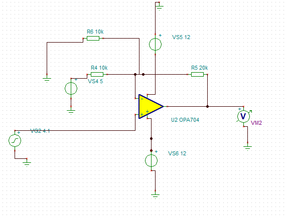
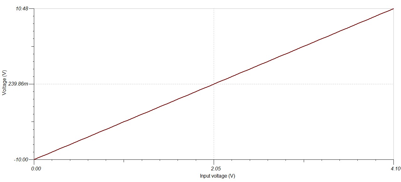
I would like to amplify a Unipolar 0 - 4.096V to a Bipolar ±10V signal.
I tried filtering the amplifiers, but there is no option to choose input/ouput ranges. Can someone help me?
The signal is coming from a DAC 12-bit
Best regards,
Luc
Hi,
I would like to amplify a Unipolar 0 - 4.096V to a Bipolar ±10V signal.
I tried filtering the amplifiers, but there is no option to choose input/ouput ranges. Can someone help me?
The signal is coming from a DAC 12-bit
Best regards,
Luc