This thread has been locked.

If you have a related question, please click the "Ask a related question" button in the top right corner. The newly created question will be automatically linked to this question.

[FAQ] INA3221: Input Bias Current & Impedance Specs for Bus Voltage Monitors

Part Number: INA3221
Other Parts Discussed in Thread: INA219, INA231, INA230, INA226, INA220

Some power monitors contain "input bias current || input impedance" specifications. How do these properties affect design and implementation of these devices? Some of these devices include INA3221 and INA219.

  • When reading the INA219 datasheet you will find the input bias current specification is different for each input:  IN+ = 20µA and IN-= 20µA||320kΩ. The IN- pin has an input impedance of 320kΩ, creating an imbalance in the input pins of the device (IN+/IN-).

    The following information applies for INA3221 as well. The INA3221 input bias current specifications are the following: INA3221: IN+ = 10µA and IN-= 10µA||670kΩ.

    Essentially this specification means there is a resistance from pin IN- to GND. This resistance is what the amplifier senses the bus voltage from since a little current will be drawn (sunk) into the pin through the 320kΩ resistance and measured as a voltage. Because of this as the common mode voltage increases, so does the difference between the IB+ and IB- currents or Ios (input offset current). Normally this does not affect system/device performance because you will be measuring a much larger current than IB, but as soon as external input resistors are added, an input voltage offset will be induced and affect device accuracy unless this new offset is calibrated out for a particular VBUS value.


    Effects of adding external input filtering to INA219 due to the IN- pin input impedance

    Adding an external filter at the inputs of the INA219 will affect your current measurements due to this input impedance. The external filter resistors (Rfilter1/Rfilter2) in combination with the input impedance will create an additional voltage drop across the inputs.

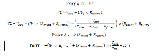
    The new voltage drop (with no load) can be calculated using the following formula:

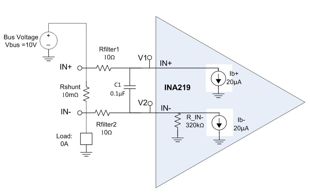
    Example:

    The only voltage expected in Vshunt with No Load (0A) is the offset voltage specified in the datasheet (20µV typical). This voltage change when we add series resistors in the input of the INA219.  The following example calculates/simulate the voltage drop in Vshunt with no load (0A load).

    • Bus Voltage = 10V
    • Rshunt = 10mΩ
    • Rfilter1=Rfilter2=10Ω
    • Ib+ = IN+ input bias current = 20µA
    • Ib- = IN- input bias current = 20µA
    • RIN- = IN- input impedance = 320kΩ 

    Calculation: 

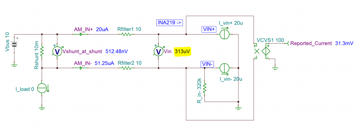
    Simulation: 

    As calculated (and simulated), the addition of Rfilter1 and Rfilter2 created a higher offset at the input pins. This higher offset will affect the accuracy of the device significantly.  

    Solution:

    For this reason, we recommend you avoid using input filters when dealing with the INA219 or INA3221 devices. If your application requires input filtering we recommend you take a look at INA220, INA226, INA230 and INA231. These devices have a separate VBUS pin for measurement that doesn't imbalance the IN+/IN- inputs.

    Related Forum Posts: