This thread has been locked.

If you have a related question, please click the "Ask a related question" button in the top right corner. The newly created question will be automatically linked to this question.

[FAQ] INA250: Adding TVS Protection diodes

Part Number: INA250

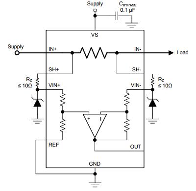
I want to add transient voltage spike protection to my current sense amplifier circuit and considering adding TVS protection diodes.  Is there any considerations I need to take into account.

  • Should you include TVS protection diodes in your circuit?

    Example INA250 schematic with TVS protection diodes

    In the above simplified circuit diagram, TVS diode (tranzorbers) are incorporated to the input pins of the INA250, as often recommended for situations where excessively high transients might be present.  (Transients are spikes or fast, momentary changes in input signal with amplitude greater than the specified maximum input voltage.)

    These TVS diodes should effectively clamp the input voltage when used in conjunction with series resistors to protect the amplifier circuit. This topic has been addressed thoroughly in TIDA-00302

    However, care should be taken when the input signal is PWM (and just a side note - PWM signals should not be used with the INA250; see this FAQ post.) In these situations, the large junction capacitance of the diodes tends to cause oscillation.

    Spice simulation schematic of source and TVS diode

    In the above schematic, the components enclosed by the rectangle (Vin, R1 and L1) represent the source and PCB parasitic; R2, R3 and D1 represent protection devices added to the INA input pins.

    Spice simulation showing ringing without dampening resistors R2 and R3

    When R2 and R3 are not included in the schematic, sustained oscillation can be seen on the input to the INA.

    Spice simulation showing ringing with dampening resistors R2 and R3 included

    The above plot shows that damping resistors R2 and R3 greatly suppress the oscillation.

    The general recommendation is NOT to use any protection devices if at all possible to maintain signal integrity.

    If this is not an option and protection diodes must be used, properly sized series resistors should be used to dampen the potential oscillation. The resistor value will depend on the diodes chosen. It should be noted that the added resistance may negatively impact the accuracy of the INA.

    For more information on how series resistors impact the accuracy of the amplifier, video 8 on input filter errors of the Getting Started with Current Sense Amplifiers video training series