This thread has been locked.

If you have a related question, please click the "Ask a related question" button in the top right corner. The newly created question will be automatically linked to this question.

TLV9061: Question about Bandwidth Limit.

Part Number: TLV9061
Other Parts Discussed in Thread: OPA322, TL431, TLV9062

Hello team,

We intend to promote TLV9061 to my customer to replace OPA322, their application would be a feedback error amplifier, but RD is concerning about TLV9061 BW=10MHz is lower than OPA322 BW=20MHz which may have potential risk.

Can you comment if TLV9061 is OK for error amplifier application? any concerning about BW=10MHz?

The power supply system working frequency is 65KHz, so the fco should be < 6.5KHz.

Thanks,

MartinSchematic_OPA322 error amp..pptx

  • Hi Martin,

    Do I understand that the required system bandwidth is 65kHz? What type of gain do you need? As long as the product of the gain and the circuit bandwidth is less than 10MHz than generally you should be okay.

    If you can attach a schematic that would be helpful. We'll be able to review the schematic and let you know if there are any stability concerns by going to a lower BW part.

    Thanks,
    Paul
  • I already attached the schematic, don't you see that?
  • My apologies, I missed that. I'll review it and get back to you.

    Thanks,
    Paul
  • Hi Paul,
    It's OK.
    If 65KHz is OK, please also tell me the allowed max working frequency that TLV9061 can handle.
    Thanks,
    Martin
  • Hi Martin,

    I will do that. I don't see what the value of S_AVDD is. Can you provide that?

    -Paul
  • Hi Paul,
    It's a 3.3V supply.

    Martin
  • Hi Martin,

    I have a couple of concerns about this schematic.

    First, with S_AVDD=3.3V, D471 will be forward biased nearly all the time which seems incorrect. This is based on the assumption that IN- to the op-amp will be at 6V or higher (common mode of the op-amp is 6V from the 12V_REF pin).

    Second, the circuit for Vref takes a 12V reference and divides it down to 6V which is much higher than S_AVDD and will cause the ESD cells in the op-amp to turn on. This voltage needs to be in the common mode range of the amplifier.

    Finally, usually we see these types of circuits in a servo loop - can you share with me the rest of the circuit so that I can properly simulate it and show you the results between the two devices? If I can see what generates the 12V_DET voltage and where 12V_FB goes to, that would be very helpful.

    Thank you,
    Paul
  • Hello Paul,

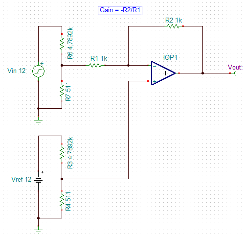
    Here I re-attach the schematic to answer your question, according to the feedback resistor divider, we can easy to come out the IN- voltage would be around 1.1V, rather than 6V. and also the 12V_REF is just a node name, it's not 12V level, actually, it comes from digital controller and purpose to fine tune the output voltage.

    Please let me know if anywhere is unclear.

    Please help to verify this design.

    Thanks,

    Martin

    1588.Schematic_OPA322 error amp..pptx

  • Hi Martin,

    I guess then I'm still having a little trouble understanding. What is the range of magnitudes that 12V_REF can be? Is it normally 0V?

    -Paul
  • Hi Paul,
    Of course not, how comes normally 0V? if it is normally 0V, then output would be 0V as well, isn't it?
    Of course it definitely almost equal to IN- (around 1.1V), thus output would be ~12V, and the range is pretty tight should be around 1.0V~1.2V, the purpose is to fine tune the output voltage to be very close to 12.00V in factory by every single server PSU.
    Can you help to review the design?
    Thanks,
    Martin
  • Hi Martin,

    For a inverting op-amp configuration like this one, the common mode voltage is set by the voltage on the non-inverting pin of the op-amp.

    This circuit is strange to me because like I mentioned earlier, we normally see this type of circuit with capacitors as the feedback path being used as integrator circuits and for circuits like the one shown in Figure 2 of this document.

    If you just want to take the difference between the input 12V signal (divided down to 1.1V) and compare it to a 1.1V reference, why not simply use a circuit like this?

    We have a cookbook circuit that discusses this type of circuit as well.

    The most important question you can answer is what type of signal does 12V_FB need to be? Is it simply the difference between the input and the reference? Or is there some necessary integrating function?

    Thanks,

    Paul

  • Hello Paul,

    No, your schematic is a DC amplifier, but actually my customer's circuit is an error amplifier. they are totally different.

    My customer's circuit is a power supply schematic, similar to attached slide 2, in most of cases, TL431 is used as feedback loop which has internal fixed 2.5V reference voltage, this can control system to regulated output voltage. and meanwhile it needs external RC network as loop compensation to avoid unstable oscillation happen.

    However, in my customer's case, they are using OPA322 as error AMP with digital controller's adjustable reference voltage in stead of TL431, as I mentioned, this adjustable VREF is purpose to obtain a more accurate output voltage. hopefully this can help your understanding.

    As I mentioned previously, their power supply has 65KHz switching frequency, in terns of power supply stability principle, the cross over frequency should be less than fsw/10=6.5KHz, so actually, the fco they have is around 5KHz.

    Based on above information, can you help confirm that if TLV9061 BW=10MHz is good enough to instead of OPA322 BW=20MHz? this is my major support need, please help.

    Thanks,

    Martin

    4426.Schematic_OPA322 error amp..pptx

  • Hi Martin,

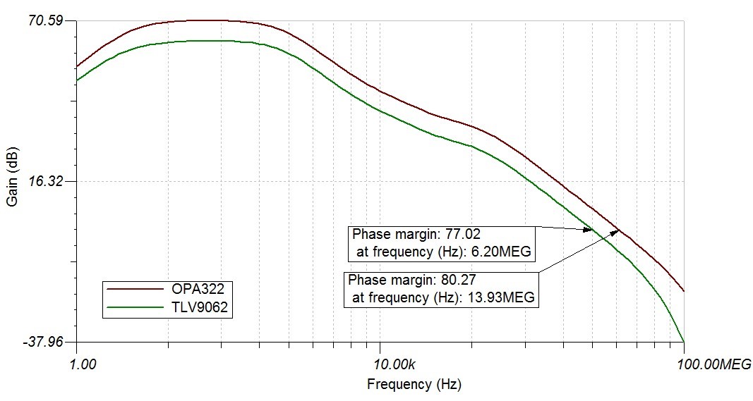
    Thank you for taking the time to help me understand your circuit in more detail. I was able to simulate this circuit and get the results you are looking for.

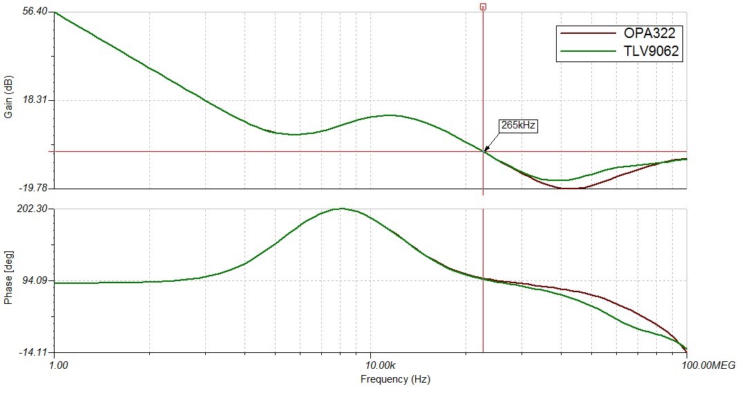
    Comparing the OPA322 and the TLV9062, the results are basically identical. In analyzing the loop gain and stability of the overall system, there is only a slight loss of phase margin - only 3 degrees.

    Comparing the forward gains of the system (closed loop), we can see that they are basically identical until about 265kHz which is well outside the bandwidth of the power supply.

    As long as the customer is happy with their OPA322 solution and it functions as well as they would need, then there should be no issues with the TLV9062.

    I've attached the simulations for you look at.

    Best,

    Paul

    ErrorAmp.zip