This thread has been locked.

If you have a related question, please click the "Ask a related question" button in the top right corner. The newly created question will be automatically linked to this question.

INA129: INA129 Input Bias Current Return

Part Number: INA129
Other Parts Discussed in Thread: ADS124S08, INA128

Dear Sir,

I have  questions about the subject. INA129 d/s has section 8.2.2.4 description and three examples of Figure 26.

1) Does this current return path is not necessary for  DC coupled signal source?

2) How to calculate the right resistance value (example is 10Kohm in figure 26) for thermocouple?

3) Does it require for RTD source? INA129 is put between RTD Lead resistances (100ohm each) and ADS124S08 inputs. 

4) if yes, which one or two resistances will be connected? And how to calculate return path resistance value?

4) and if there is more detail technical description, application note and etc. it will be very nice to have.   

Best regards,

Masa

  • Hi Masa,

    I'm not quite sure what you mean. Can you show a schematic of your circuit?

    Kai
  • Hi Kai,

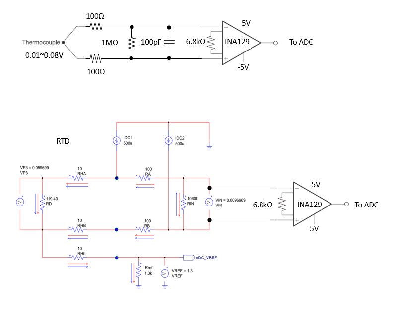
    I am attaching thermocouple and RTD schematics below

    Best regards,

    Masa

  • Hi Masa,

    the biasing resistor (10k) is chosen so that the source resistance of thermocouple (30...100R) does not erode the common mode rejection of INA129.

    The scheme with the RTD does not need an additional biasing resistor. The 1k3 resistor (Rref) plays this role.

    Kai
  • Hi Kai,

    Thank you very much for your explanation. I understand RTD does not need. I still would like to understand thermocouple case.

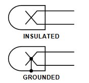
    Is it same reason for thermocouple as a floating input source of  AC coupling with each input capacitor and with transformer?

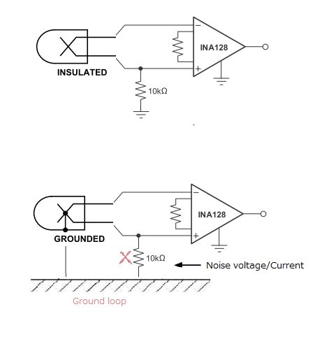
    If it is not insulated but grounded thermocouple type it will not be necessary to avoid ground loop, correct?

    And how to calculate/estimate the return path register value?  Can it be higher than 10Kohm even 1Mohm for ground connection?

    Best regards,

    Masa

  • Hi Masa,

    assume your measuring object is contaminated with interference voltage, noise and transients and you don't want that noise being injected into the signal ground. That's the moment when you think about using an instrumentation amplifier like the INA129.

    The interference voltage of measuring object appears as common mode noise and reaches both inputs of INA129. In order to not erode the brilliant common mode rejection of INA129, you must take care that the biasing resistor connected to one leg of the thermocouple does not transform common mode noise into a differential noise. As the common mode rejection ratio of INA129 is about 125dB below 200Hz at a gain of 100, according to datasheet, you want a "common mode rejcetion" of your biasing resistor which is better than 125dB.

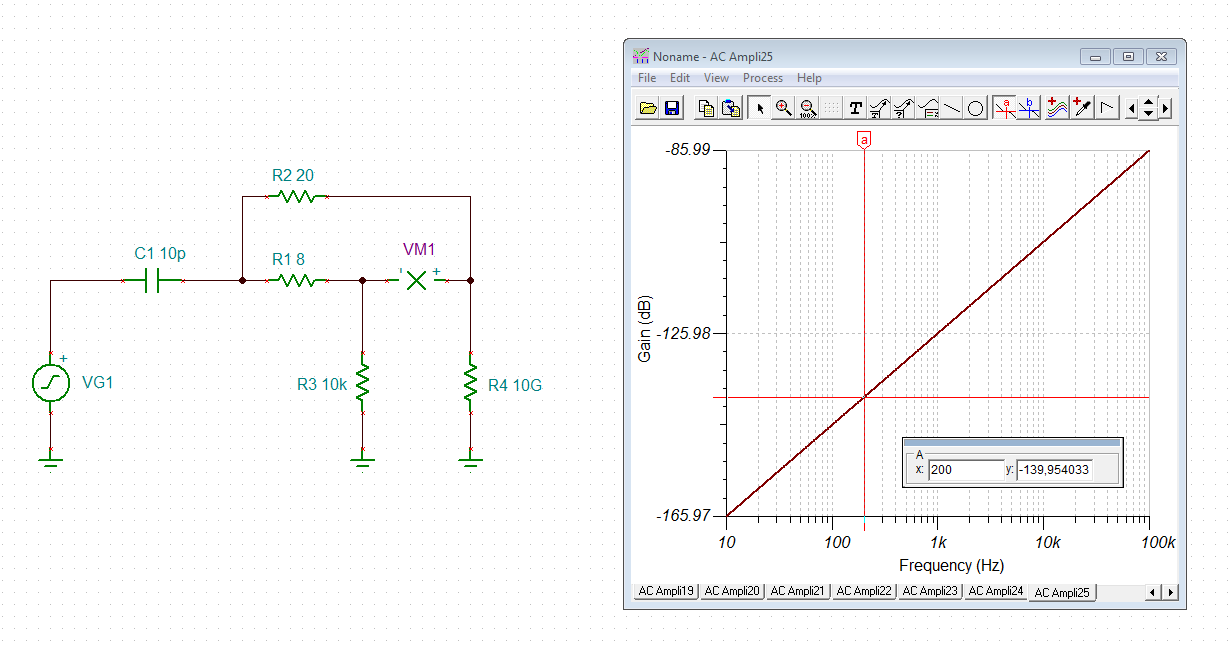
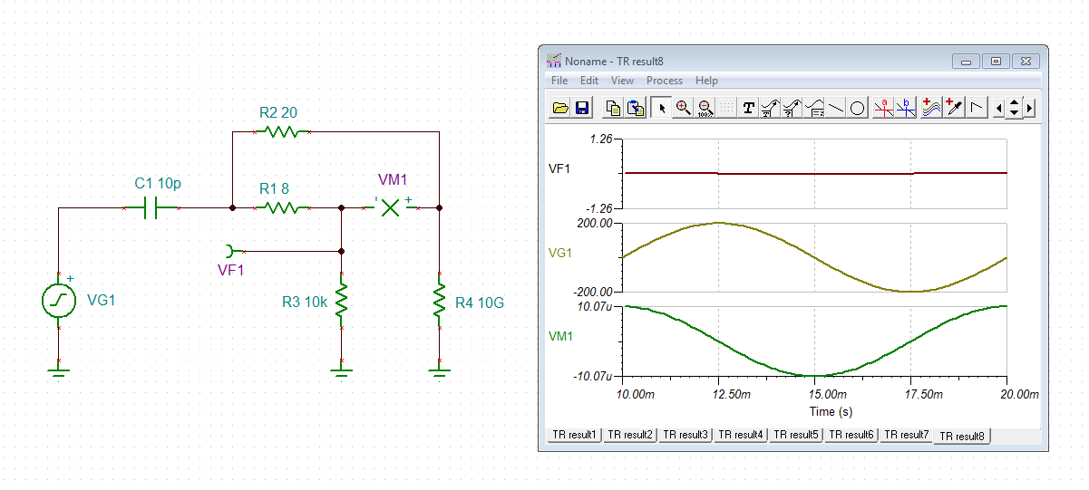
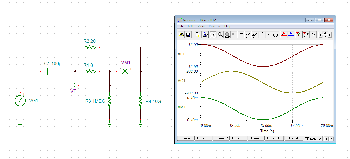
    The following simulation shows an application with a stray capacitance between the sensing point of thermocouple and measuring object of 10pF and a biasing resistor of 10k:

    You see that the common mode noise is suppressed by more than 140dB below 200Hz. So, this is a good scheme and the biasing resistor is chosen properly.

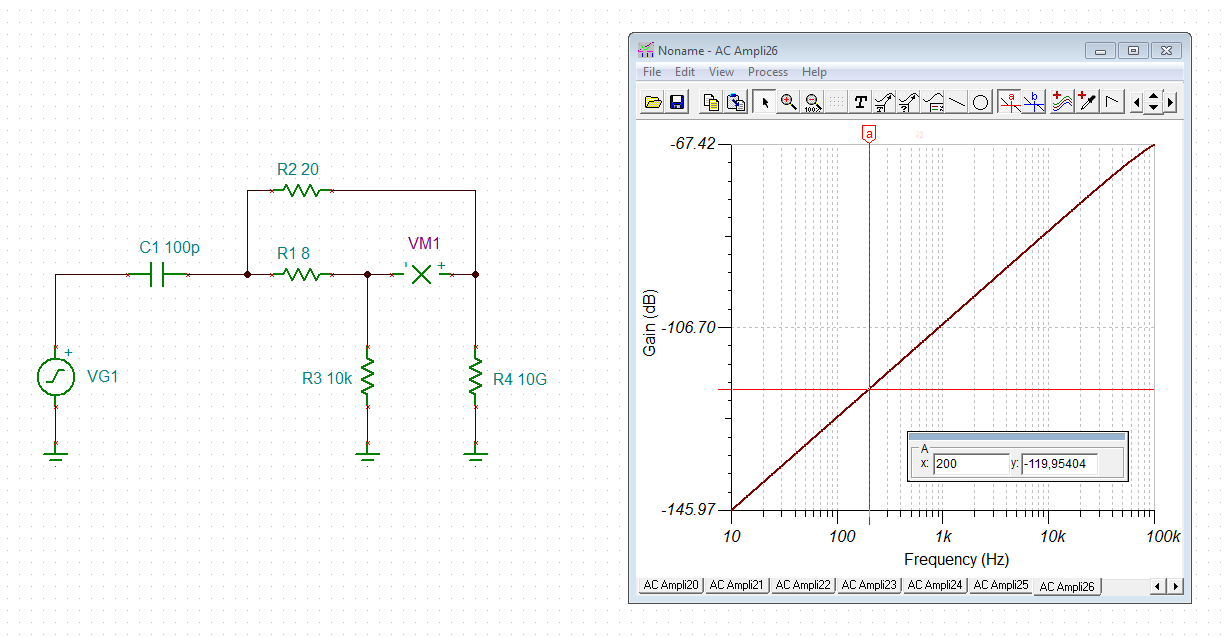
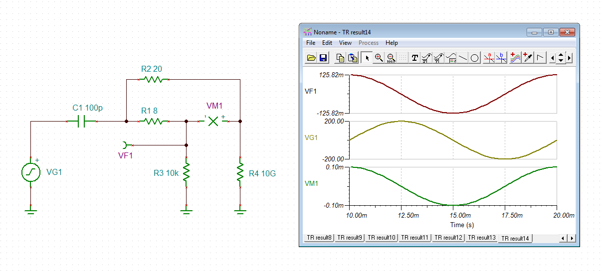
    But if the stray capacitance between the sensing point of thermocouple and the measuring object is higher, let's say 100pF, you will get the following simulation:

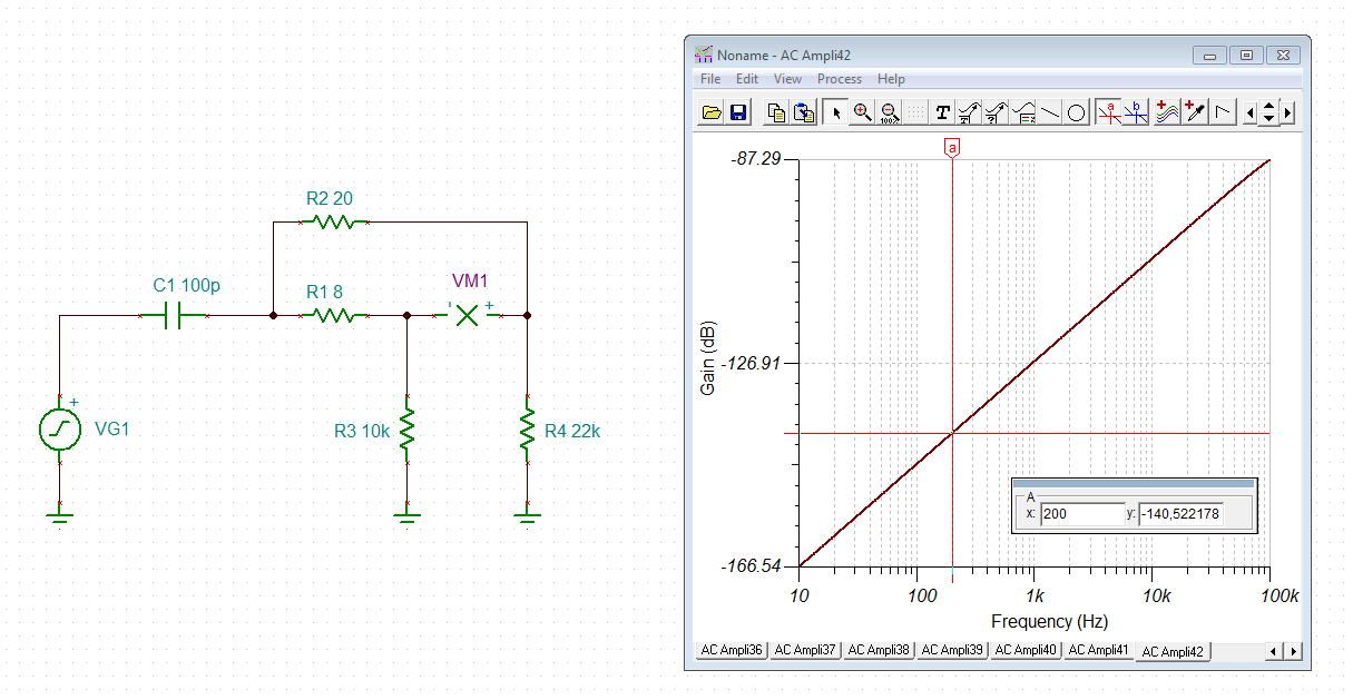
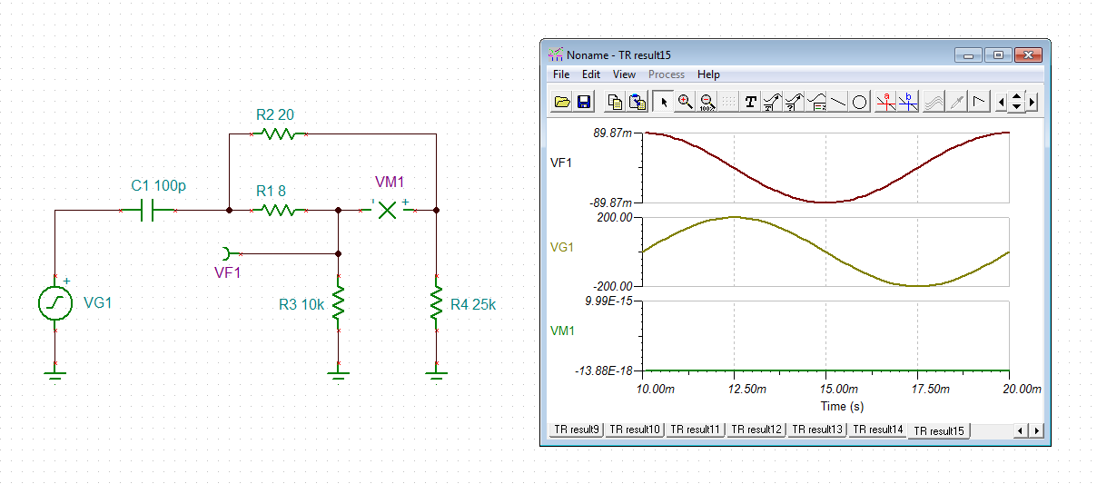
    The common mode suppresssion is only 120dB now and will degrade the performance of INA129. In such a case it might be useful to add a biasing resistor also to the other leg of thermocouple:

    Even if the impedance matching isn't perfect (22k instead of 25k), you will get a considerable boost in common mode suppression!

    A note to the thermocouple: I measured a typical resistance of 8R in the - wire and 20R in the + wire of type k thermocouple, each between the sensing point and the plug.

    Kai

  • Hi Kai,

    Thank you very much for the thermocouple wire model and simulation.

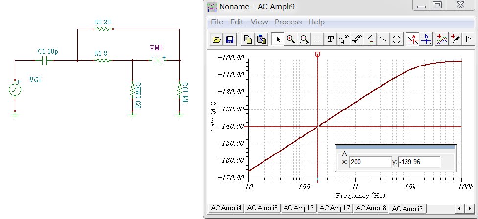
    I simulated and got almost same CM suppression 139dB with R3 = 1M  instead of 10K.

    I wonder if the 10Kohm of return path resistance value is decided by another reason to discharge INA129 input charged voltage by bias current through C1, correct?

    INA129 bias current is very low then charge rate is quite fast that makes common voltage may drift well, then gained INA129 output will get impact the drift if R3 is not enough low to discharge the CMV drift.

    I would like to know how 10K is decided in the INA129 data sheet. 

    And if I use grounded thermocouple, should I NOT have  the return path resistance to avoid a ground loop?


    Best regards,

    Masa  

  • Hi Masa,

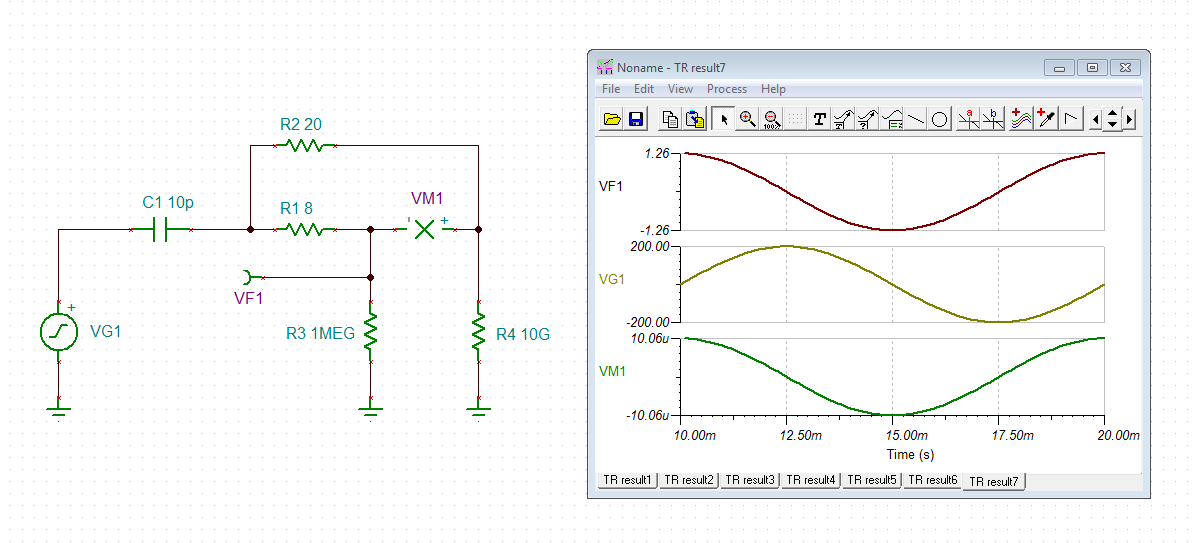
    the usual technique is to make the biasing resistor as small as possible and as big as necessary. Increasing the biasing resistor increases the absolute value of common mode noise the OPAmp has to withstand. So, it's not wise to increase the biasing resistor too much:

    In the following simulation the situation with a the stray capacitance of 100pF is shown:

    masa.TSC

    I haven't understood your last question.

    Kai

  • Hi Kai,

    I would appreciate for your simulation again. I understand a trade off to CM noise. The 10K does not come from a specific formula.

    About the ground loop question is as follows;

    Best regards,

    Masa

  • Hi Masa,

    if the sensing point of thermocouple is grounded (protective earth), then it depends on the voltage difference between this point and the signal ground of INA128 (signal common), how to proceed. This voltage difference appears as common mode noise at the input of INA128. If the common mode noise is not too high, the INA128 might be able to handle it. But in any case the biasing resistor is needed and has to be connected to signal ground of INA128, as shown above.

    But if the common mode noise is too high, a different approach should be followed: I would directly connect the ground of sensing point of thermocouple with the signal ground of INA128. The cable shield of thermocouple wiring could be used for that. This would provide an equipotential bonding between the thermocouple and the INA128 and eliminate most of the common mode noise. Then, the two signal wires of thermocouple should be connected to the INA128 in the same way as shown above.

    BUT: To prevent ground loops the signal ground of INA128 (signal common) which has the same potential as the thermocouple ground (protective earth) now, must not be connected to the signal ground of rest of system, unless it is powered from a floating supply. If the signal ground of the rest of system is also connected to protective earth, an isolation amplifier between the INA128 and the rest of system should ne used.

    Kai

  • Hi Kai,

    I really very appreciate for your thoughtful advices even it was not within amplifier but system level question including sensor itself.
    I understand the noise issue very much and INA129 will give an advantage on noise reduction with the bias current return path as well and will support any type of thermocouples including grounded one with its negative rail.

    We are considering ADS124S0x of configuration with and without INA129. The ADC is very friendly to all kinds of sensing including RTD and so on with IDAC and VBIAS.

    Of course the bias current return path will be VERY helpful for either configuration that I understand from your explanation.

    Best regards,
    Masa