This thread has been locked.

If you have a related question, please click the "Ask a related question" button in the top right corner. The newly created question will be automatically linked to this question.

OPA4227: OPA4227/integrator/Quadrature Oscillator

Part Number: OPA4227
Other Parts Discussed in Thread: TLV2474, TINA-TI, LM317, LM337, LM13700, TLV2472, UAF42

Hi,

I have designed an integrator based Quadrature Oscillator as per the TI application note on Sine-Wave Oscillator (section 8.5) using opamps OPA4227. As per the application note oscillator output seems fine and  my simulation output also looks clear. But, In my design on PCB, I am getting intermodulation distortion at the output of Oscillator inspite of following all good PCB design rules to avoid any supply noise, coupling noise etc. Can anyone pls tell me what could be the reason for it and how can I overcome this problem..

  • Hello Shambhulingayya,

    It would be helpful if we have the complete schematic for you OPA4227 quadrature oscillator circuit. Please include the supply information and any images you have captured of the quadrature output signals showing the intermodulation distortion (IMD).

    IMD results from the mixing of two, or more, different frequencies. Since this is an oscillator circuit it is most probable that any IMD would be the result of the fundamental frequency mixing with one of its harmonics. For example, the third harmonic mixing with the fundamental such as f1 + f3, etc. We need to determine if it actually IMD, or some other kind of distortion.

    Regards, Thomas

    Precision Amplifiers Applications Engineering

  • Thank you so much Thomas for the reply.

    Yeah, here is the supply info...

    Lithium ion battery supply, +/-5V, generated using 7805/7905 voltage regulators. I have checked supply noise in the DSO and seems to be fine.

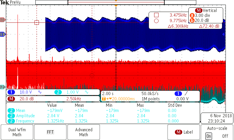
    Please find the attached image and video of the outputs...

  • Hello Shambhulingayya,

    I still need to see the complete schematic for your quadrature oscillator circuit. I understand your power supply arrangement, but don't know what frequency you are attempting to generate, or what component values have been used in the circuit.

    The blue waveform you provided looks more like an amplitude modulated envelope with a low frequency modulating a much higher frequency. The red FFT  display is possibly only for the low modulating frequency and not for the much higher frequency content. If that is the case, the OPA4227 may be oscillating at a much higher frequency than the intended frequency. The output of the quadrature oscillator should just be sine and cosine waves at the intended frequency and not the modulated envelope.

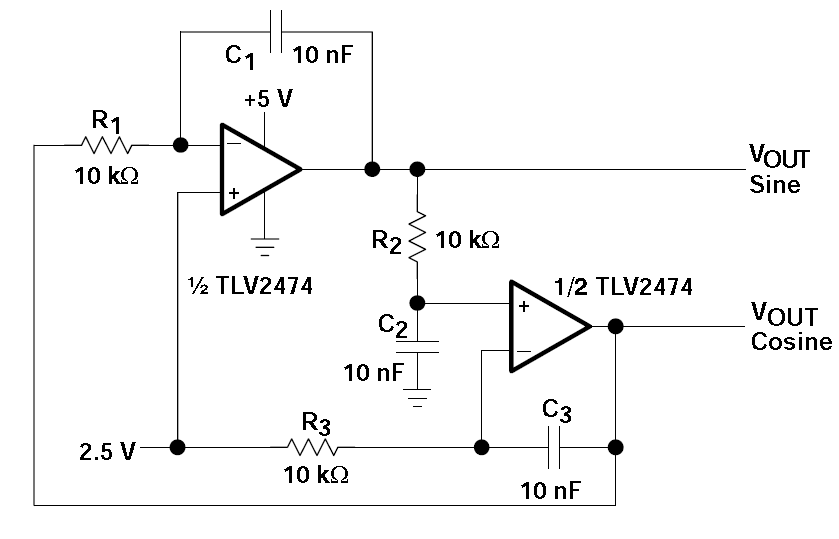
    The original op amp used in the published TI quadrature oscillator circuit was a TLV2474, a CMOS rail-to-rail input/output op amp. The OPA4227 is bipolar op amp that is not rated as rail-to-rail input, or output. Since the simple quadrature oscillator circuit in the article does not have any automatic gain control (AGC) the OPA4227 input common-mode voltage (VCM) range of the cosine stage may be exceeded. If that happens the op amp behavior may not be as otherwise expected. Also, since the output is not rail-to-rail hitting the rails causes the open-loop gain to collapse and destroys the normal, linear operation of the op amp.

    I suggest trying the TLV2474, or another suitable CMOS rail-to-rail op amp in the circuit and see what result you obtain. If the circuit still produces the modulated envelope output with a rail-to-rail op amp, then there is something else not quite right with your circuit.

    Regards, Thomas

    Precision Amplifiers Applications Engineering

  • Shambhulingayya

    We haven't heard back from you so we assume this answered your question. If not, just post another reply.

    Thanks
    Dennis
  • Hi Thomas,

    Thank you so much for elaborate explanation. Yeah sure, I had ordered TLV2474 and waiting for it's delivery. But, one observation is that, I have simulated the circuit using TINA-TI with OPA4227 macromodel where I didn't see the problem of intermodulation. Any idea why did it work in simulation even though I used  OPA4227 macromodel which is not an input rail to rail OPAMP?.

  • Hi Shambhulingayya,

    Thomas has asked you two times to give us a schematic of your circuit.

    No schematic, no help...

    Kai
  • Sorry Kai,

    I am using exact same schematic as it is in TI application note on Sine-Wave Oscillator (section 8.5). Here it is...

  • Hi Shambhulingayya,

    I cannot make the circuit run in TINA-TI at all. Can you give me your TINA-TI file?

    Kai

  • Hi Shambhulingayya,

    thanks, it works now!

    Nevertheless, I see lots of distortion with the OPA4227, mainly at the cosine output. With the TLV2474 the distortion is much lower, nearly invisible. So, I aggree with Thomas, that you should give the TLV2474 a try.

    But don't expect too much from this quadrature oscillator. As it does not contain a true amplitude stabilization, there will always be a certain distortion.

    Kai
  • Hi Thomas and Kai,

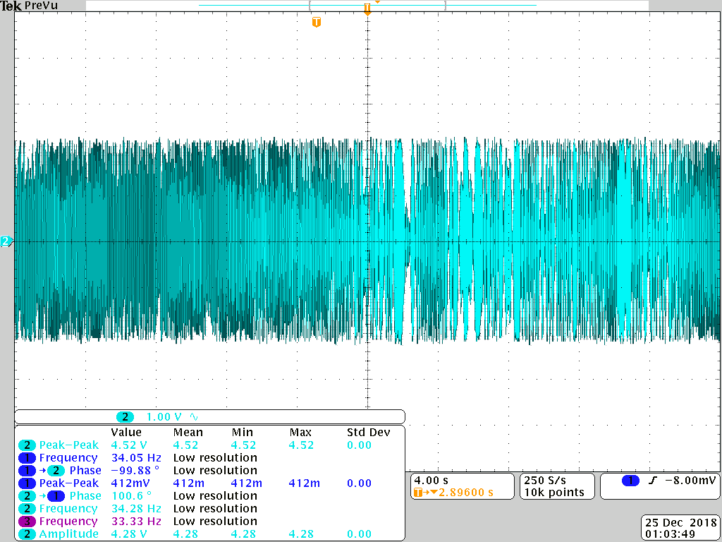
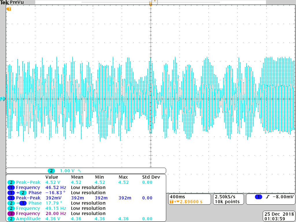
    As you suggested I tried  TLV2474 with Kethley DC voltage supply, but still there exists  the problem of intermodulation and amplitude instability (P.S, in the attached file). Now I am quite curious to know what causes this intermodulation and amplitude instability inspite of having OPAMP with rail to rail input which inturn ensures the linearity. It would be great if you could explain it...

    Thanks :)

  • Hi Shambhulingayya,

    are the +5V and -5V supply voltages clean and stable?

    Can these be artefacts from your scope? Start with very small horizontal time constants and increase in small steps.

    You should not directly touch the output of OPAmp with the scope probe. Insert a small resistance of about 100R.

    Kai

  • Hi Kai,

    Currently I am using Kethley DC power supply +/- 3V which is relatively stable but, I can see 50Hz noise from supply. But, apart from 50Hz noise I was also able to see other frequencies (bcoz of intermodulation) and amplitude unstability . I wanted to use battery supply with +/-3V as TLV2474 operates below 3V but, I didn't find +/-3V voltage regulators from TI. Hence, I used DC power supply from Kethley. If you know any voltage regulator with output less than 3V and greater than 1.5 V pls let me know. BTW, I don't think there are artifacts from scope as DSO and the probes I am using are in a very good condition and I have I also verified this by checking the outputs of function generator on the SCOPE which was very clear. I didn't get what do you mean by "Start with very small horizontal time constants and increase in small steps", can you pls elaborate on it?

    Thank you

    Shambhu

  • Hi Shambhulingayya,

    I meant that you should set the timebase (horizontal scale) first to 1µs/DIV, then to 2.5µs/DIV, then to 5µs/DIV, then to 10µs/DIV and so on. This avoids these confusing beatings between the signal frequencies and the DSO sampling rate and other sampling artefacts (aliasing).

    You could use the LM317/LM337 to produce supply voltages lower than +5V/-5V.

    Kai

  • Hi Kai,

    PFA DSO outputs with different time constants ranging from 1 uS to 10 S. BTW, to answer your previous question, between OPAMP outputs and DSO probes I have used unity gain buffers and is that I need to insert 100 Ohms resistor even after using buffers?

    8780.outputs-at-different-time-constants.zip

  • Hi Shambhulingayya,

    please read section "Driving A Capacitive Load " on page 15 of datasheet of TLV2474 and see figures 41, 42 and keep in mind that a scope probe presents a capacitive load to the output of OPAmp.

    Kai
  • Thank you Kai. I got it and wil try it now.

    BTW, parallelly I am looking for other architectures of quadrature oscillators like LC based. Can you pls suggest if there are any ICs of quadrature oscillators based on LC.

    Thank you

    Shambhu

  • Hi Shambhulingayya,

    do you only need a sine wave generator? Or do you need a combined sine wave and cosine wave generator?

    Kai

  • Hi Kay,

    I need a combined sine wave and cosine wave generator. This I am going to use for I and Q generation.

    Thanks
    Shambhu
  • Hi Shambhulingayya,

    and what frequency do you need?

    Kai
  • Hi Kai,

    I need low frequency anything between 200Hz to 1.5kHz should be fine. This is for lockin amplifier applications.

    Thanks
    Shambhu
  • Hi Shambhu,

    for a lock-in application you only need square waves, right? Then I would do it with two flip flops, as shown here:

    www.markimicrowave.com/.../

    Kai
  • No Kai, sorry, currently we already have a square wave but, wanted to change it to single tone sinusoidal for some reasons. So, need a single tone sine wave and cosine wave generator.

    Thanks
    Shambhu
  • Hi Shambhu,

    another idea of building a quadrature oscillator is to use an OTA like the CA3080 or LM13700, as shown here:

    www.experimentalistsanonymous.com/.../LM13700 sine wave VCO.pdf

    Or you could take a sine-cosine generator using a state-variable filter with amplitude stabilization, as discussed here:

    sound.whsites.net/.../sinewave.htm

    Kai
  • Thank you so much Kai. Let me go through them...
  • Shambhu

    We haven't heard back from you so we assume you were able to resolve your issue. If not, post another reply.

    Thanks
    Dennis
  • Hi Dennis,

    As it is in the previous conversation, an issue of intermodulation is not yet resolved and Mr Kai then suggested me not to rely on this quadrature oscillator (one I made as described in TI application note on Sine-Wave Oscillator [section 8.5]) and later he referred me to use some other quadrature oscillator architectures which I am exploring.

    Thanks
    Shambhu

  • Hi Shambhulingayya,

    When I review the various DSO images you captured I still come to the conclusion that the waveform is that of an unintended oscillation condition, and not that of the intended, controlled frequency output. The original TI Analog Applications Journal article by Ron Mancini, describes the conventional op amp quadrature oscillator circuit that has been around at least 5 or 6 decades and the knowledge of it is not unique to TI. There is an MIT on line resource that shows the very topology used in Ron's circuit. You can find that resource here:

    If the issue plaguing the TLV2472 circuit is an unexpected oscillation it is due to something outside the realm discussed in Ron's and the MIT resources, and would require additional investigation.

    I ran a TINA Spice simulation on the two op amp TLV2472 quadrature oscillator and observed something unexpected. The circuit initially oscillated at the expected frequency, but then the oscillation damped out in about 60 ms. I don't know if the actually circuit would exhibit this behavior, but if it does that might explain the absence of the expected oscillation, and sine and cosine wave outputs. It might be due to some deficiencies in the TLV2472 simulation models. You can see that result here:

    Ron mentioned another quadrature oscillator circuit in his article called the Bubba oscillator. I wanted to see if it exhibited the same damped output behavior as the original circuit. When I simulated the Bubba circuit it provided sustained sine and cosine output waveforms as long as I biased the op amp common-mode voltage more towards the middle of the supply range. You can see that result here:

    One issue that I find with this result is the output amplitude for the sine and cosine outputs is somewhat different, but I believe that can be the case for quadrature output oscillators. I think I would be inclined to try this circuit and see if you are successful in achieving the outcome you are after.

    Here's my TINA Spice file if you would like to try simulating the Bubba oscillator circuit:

    TLV2472_Bubba_Osc_01.TSC

    Regards, Thomas

    Precision Amplifiers Applications Engineering

  • Thank you Thomas for reply and sorry for my late reply...

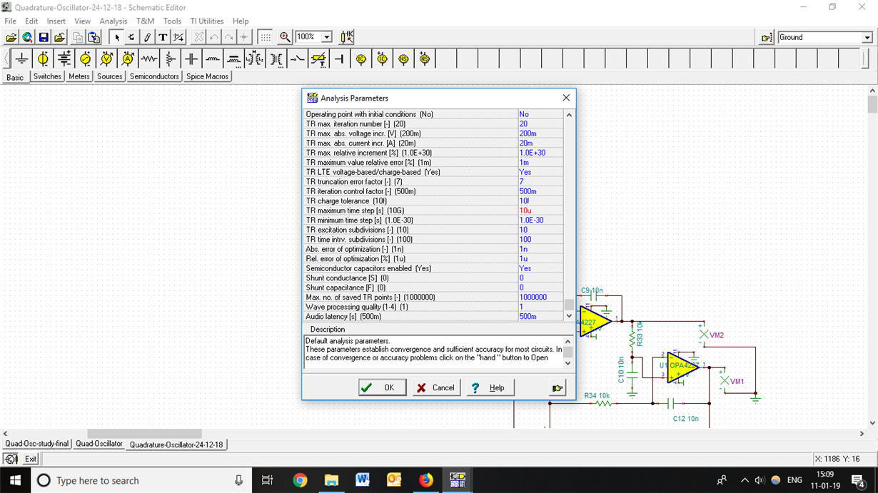
    I think, the damped output that you are getting is because of the TINA TI setting issues. For the settings pls, go to Analysis --->Analysis Parameters ---> TR maximum time step (change it to micro or nano)...

  • Hi Shambhulingayya,

    Yes, the TR maximum step that was the issue behind the damped output from the quadrature oscillator seen in the TINA simulation. I haven't ran into that issue before with oscillators. I found the Bubba oscillator was damping out as well if it was simulated long enough and the TR maximum wasn't reduced. It just took longer to do so.

    The TINA help information lists:

    TR maximum time step (TMAX, .Tran step ceiling value) - The time increment in transient analysis can never be more than the value specified here. Decreasing this parameter is an easy method to get finer curves and more accurate results at the expense of increased calculation time.

    TR was set to a default of 10 G, so reducing it to 10 u is a radical reduction in the time increment. Dropping it to such a low number certainly adds many more calculation points, but I am not sure why the oscillation damps out without that change. Nevertheless, it appears that the circuits readily oscillate.

    Thanks for the feedback, the TR awareness is good information to have.

    Regards, Thomas
    Precision Amplifiers Applications Engineering
  • Hi Kai,

    I am trying "sine-cosine generator using a state-variable filter" (suggested by you) as explained in application note "www.ti.com/.../sbfa013.pdf". Trying to simulate in TINA TI but not able to get any oscillations. Can you pls tell me what could be the issue in it?. Please find the attached TINA file...

    state-variable-filter-based-quad-Osc.TSC

  • Hello Shambhulingayya,

    I wasn't making much headway with the state-variable oscillator file you created in TINA so I decided to take a different approach. I had a discrete UAF42 model that I find a little easier to use and set up the state-variable oscillator circuit using it instead. I was able to get it to readily oscillate and produce the 0, 90 and 180 degree outputs but the amplitude at each output was only in the tens of microvolts. I did readjust the R1, R2 and R3, R4 ratios per the original UAF42 Applications Bulletin AB-096 and that didn't affect the output amplitudes. That resistor ratios should only affect the maximum output levels anyway.

    I adjusted the transient simulation time out for an extended time and found the issue; the oscillator takes about 0.5 seconds to start, at least in simulation. After about 0.5 seconds the output amplitude approximates the expected peak output level. The output waveforms are expected in frequency, phase and amplitudes.

    Here you can see the simulation circuit I used for the state-variable oscillator circuit I simulated with TINA:

    And here are the output waveforms showing the start up, and the steady state outputs:

    I have attached my TINA simulation file so you can try ideas you may have.

    UAF42_Quad _Osc_01.TSC

    Regards, Thomas

    Precision Amplifiers Applications Engineering

  • Thank  you so much Thomas. It works now. BTW, how did you get the  model that you used and also I am quite curious to know that why the macromodel that I used provided by TINA didn't work.

    Now, I will try the this oscillatior on actual hardware and update here as when I get the results.

    - Regards

    Shambhu

  • Hello Shambhulingayya,

    I apologize for my reply being delayed. I am currently on the road for TI and I don't have very much time during the day to participate in the e2e discussions while I am away.

    The UAF42 simulation model was developed a few decades ago by the engineering team that developed the device. I do not know the basis for the model's design, but do know I have had trouble using it as well. I certainly could reverse engineer it and try and determine its issues, but I know that would take a lot of time which I just can't spare. Rather than doing that, I decided to create the model that I used for the quadrature oscillator simulation. I have used it for other UAF42 active filter applications and it served nicely for them.

    Please do let me know if the bench version of the state variable quadrature oscillator works as needed. We have spent a lot of time going back and forth on this inquiry and it would be great to know if the new design serves your application needs.

    Regards, Thomas
    Precision Amplifiers Applications Engineering
  • Thank you Thomas for your reply.

     Currently I have ordered UAF42 IC. Once it is delivered I will try it out and will update you.

    Regards

    Shambhu

  • Shambhu

    Did you get the parts and build your circuit? Did this resolve the issue? If you have more questions just post another reply.

    Dennis