This thread has been locked.

If you have a related question, please click the "Ask a related question" button in the top right corner. The newly created question will be automatically linked to this question.

LM2907-N: Component selection confusing in the datasheet

Part Number: LM2907-N

Hello,

I'm looking to design a circuit using the LM2907 to measure the frequency of a motor.  We are designing a  safety cutoff if the motor RPMs reach 50,000, anything from 0-45,000RPMs is deemed safe.

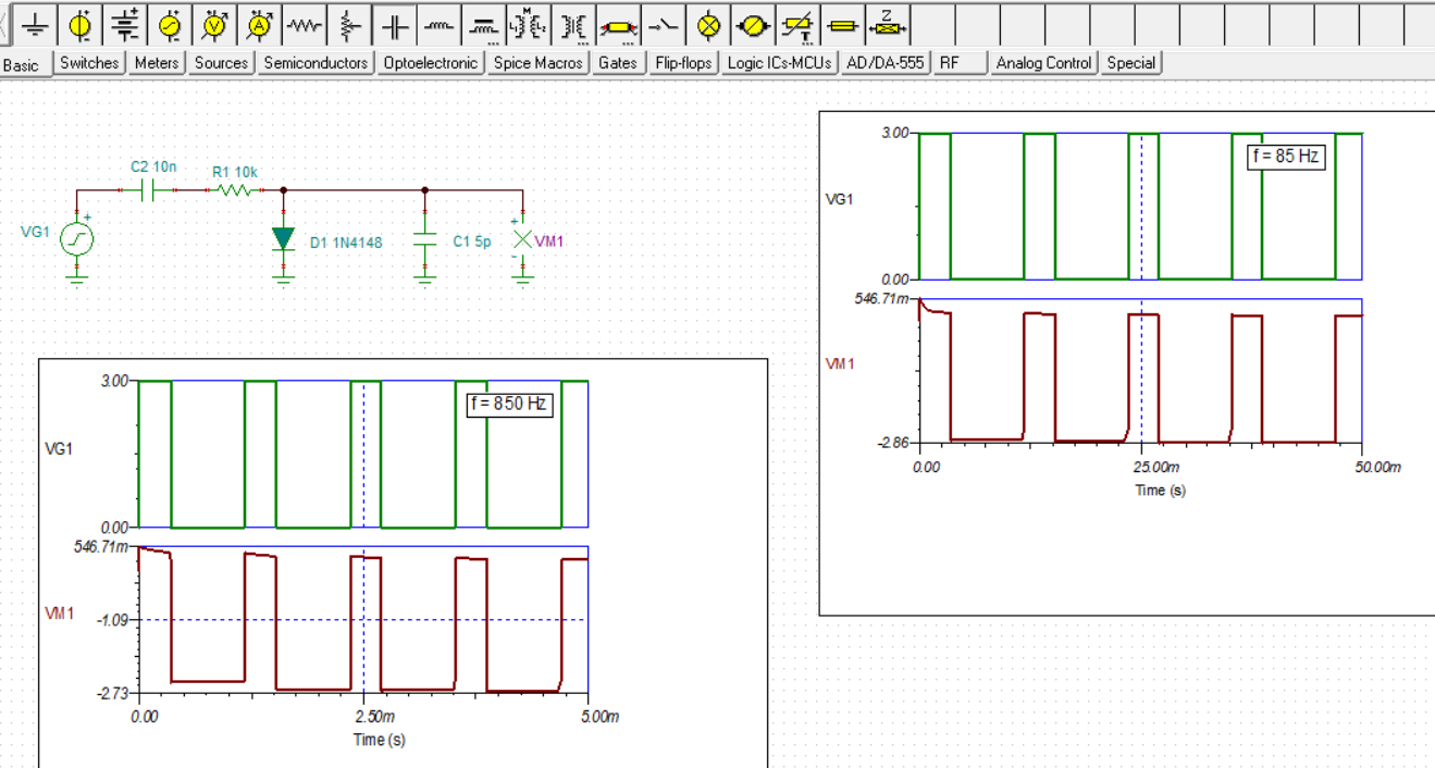
The maximum frequency will be less than 900Hz, so we should be fine to use this component.

I'd like to run the IC off of a 3.3V supply, but I can't seem to find if that's ok in the datasheet.  If not, I could run it off of 24V, but the hall signal that I'm using for the frequency input will be a square wave from 0-3.3V at roughly a 30% duty cycle, so it seemed to make sense to run the supply off that voltage too (if possible)

That leaves the selection of R1, C1, and C2.  I'm not sure what these should be set to at all.  I want to have 3V on the output at 50,000RPM, so I can trigger the motor to safely shut off.

If you can help me with the component selection I would appreciate it.  I'd also like to get confirmation that my supply voltage will be ok.

  • Hi Brandon,

    The LM2907-N is not usable with a 3.3 V supply. It is best to power it with 12 V or more, up to 28 V maximum. Your 24 V supply would be good.

    The LM2907-N has an applications note that should help you with selecting the R1, C1 and C2 values. You can find that note here:

    www.ti.com/.../snaa088.pdf

    I hope that helps.

    Regards, Thomas
    Precision Amplifiers Applications Engineering
  • Will the 0-3.3V square wave work as the input signal?

  • Hi Brandon,

    Yes. A 0 V to 3 V input is good.

    Regards, Thomas
    Precision Amplifiers Applications Engineering
  • Ok, so doing some testing and the 0-3V signal does NOT work in the circuit.  It seems that the circuit needs the input signal to drop below 0V in order for the design to work.

    In other words, a -0.1V to 3V input works, but the 0V to 3V signal does not.  What is the best way to get around this? 

  • Hi Brandon,

    Sorry I didn't better clarify the LM2907-N operation for a signal having a 0 to 3 V input range. The LM2907-N comes in two versions; one where the inverting input of the input comparator is grounded (8-pin device), and another where the inverting input is open and can be biased to a voltage above 0 V (14-pin device). The latter version is compatible with a 0 to 3 V input waveform by simply biasing the comparator's inverting input (pin 11) to a positive voltage level higher than 0 V. Datasheet Figures 20 through 22 show how a forward biased diode is applied and biases the inverting input to about +0.7 V. That would work for your 0 to 3 V input waveform. Additionally, the input could be biased to a convenient voltage level such as +1.5 V using a resistive divider, etc.

    If you must use the 8-pin LM2907 version where the comparator's inverting input is grounded, then the input signal must cross below 0 V. It appears many of automotive transducers produce an output waveform where the voltage drops below 0 V for a portion of the cycle.

    Regards, Thomas

    Precision Amplifiers Applications Engineering

  • So, I have an idea that I think would work to solve this issue. I have a +24V supply in my system, and also a +2V supply. I am using the 8 pin part, since board space is limited...

    If I tied pin 8 to my 2V supply, wouldn't that then allow me to use the 0-3V signal?
  • Hi Brandon,

    We haven't tried what you are thinking about doing. You will note that LM2907-N pin 8, for the 8-pin device shows an internal ground symbol. If you bias it at +2 V, then that becomes the LM2907-N's ground potential. I believe that the external RC components would need to be connected t the +2 V potential as well, including RL in the output emitter circuit. The output low level would then be referenced to +2 V.

    Paul Grohe, a TIer who was originally with the National Semi group that developed the LM2907-N, sent me this note:

    "He can cap-couple the input for the 8-pin for a quick-fix. The input is a 10K in series with a clamp diode, so the input ± currents will not be symmetrical if the p-p is large, so there may be a slight level shift as the frequency changes…"

    That sounds like a much easier solution if your circuit can accommodate an input capacitor.

    Regards, Thomas
    Precision Amplifiers Applications Engineering
  • I like the idea of the input capacitor. What value would you suggest? Right now the input signal is a 0-3V square wave with a duty cycle of 30%. The maximum frequency is 850Hz, and the minimum frequency is 0.
  • Hello Brandon,

    I wasn't sure about the capacitor value so I set up a couple of quick simulations. It looks like the capacitor value isn't particularly critical. You can see the results I obtained with a 10 nF capacitor at two input test frequencies, 850 Hz and 85 Hz:

    I increased the capacitor to 100 nF and it made almost no difference in the output voltage (VM1). I expect you can make the capacitor even larger and extend the low-end frequency that can be effectively coupled.

    Regards, Thomas

    Precision Amplifiers Applications Engineering

  • Thank you so much.  I have the circuit working now.