This thread has been locked.

If you have a related question, please click the "Ask a related question" button in the top right corner. The newly created question will be automatically linked to this question.

LMV641: Abnormal output while the input signal existed before device powered up

Part Number: LMV641

Hi Team,

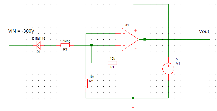
My customer used LMV641 for negative voltage detection, which VIN+ connect to V- with a resister, Vin- connect to the detected voltage via resister.

While Vin- signal(Negative Voltage) is existed before the LMV641 powered up(V+), the output of LMV kept as low, not with the expected value even the LMV641 has been powered up. Meanwhile, while the LMV641 powered up(V+) before Vin- signal(Negative voltage), the LMV641 worked as expected.


Support needs:

Could you kindly give comments for the reason that the LMV641 doesn’t work while the VIN- input signal existed before the device powered up?

  • Hi Benjamin,

    the input voltage must never go negative by more than -0.3V, otherwise latch-up can occur which can result in damage. See section 6.1 of datasheet.

    Kai
  • Hi, Kai
    is there any other amplifier can handle negative input voltage without latch-up in TI?
    we don't see the latch-up useing ADI amplifier AD8519 .
    thank you for your help.

    ( we have around -0.7V on input pin before Vcc availabe. pin current is less than 0.5mA when pin voltage is -0.7V)
  • Hi Zhongliang,

    the AD8519 doesn't allow negative input voltages either.

    Can you show a schematic of your circuit?

    Kai
  • HI, Kai

    we didn't encounter latch-up issue when using AD8519. Negetive voltage on input pin only happen before VCC apply using AD8519.

    Mayby you can suggest my other amplifier to sense negetive voltage?

    sch shows as below,  the condition is that input voltage (VIN=300v)  appeared before IC supply voltage applied.

  • Hello Zhongliang,

    When an op amp is not powered the normally reverse biased junction that keep the transistors and other elements isolated from each other are not active. When that is the case applying an input current can result in abnormal current paths being formed through semiconductor junctions that are normally turned off. Applying power with unexpected current paths established can result in latches, 4-layer semiconductor structures, being formed. They usually don't turn off until both the input current source and the power supplies are removed. If the power is reapplied and the input current isn't present as before, then the device will come up in its normal operating mode.

    Different op amps on different semiconductor processes behave differently, and may or may not exhibit latch behavior. Unpowered latch mechanisms aren't usually something that is included in the design criteria because it is considered an abnormal mode of operation. It really comes down to the particular op amp design, layout and the processing of the particular op amp IC whether it will latch or not. Even if a particular op amp isn't showing signs of latching at present there may be a future production lot where it does. There may be some rare op amps products that don't exhibit latch potential, but that may be due to unique designs relying on something such as a dielectric isolated process.

    TI does not specify any of its op amp products for use with input current flowing before power is applied.

    Regards, Thomas
    Precision Amplifiers Applications Engineering