Other Parts Discussed in Thread: TIPD209, XTR117, , OPA2317, XTR111, XTR116
Hello All,
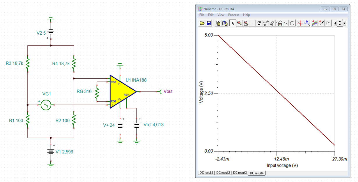
I have designed a custom board( Resistivity sensor) using the reference design (TIPD209_Hardware_E2.SchDoc). I have replicated the design as it is.At present, the input to the wheatstone bridge is a 10K potentiometer. The output of the INA188 is given to XTR117(voltage to current transmitter). I am not getting the expected output at the INA188 output pin. I am getting the variable output in the range of 7 Volts to 10 Volts(which is not sufficient).
I request you to please review the design and give the feedback on the same.
Please find the attached schematic and layout pdf.
Thanks in advance
Ankeet Gugale


