This thread has been locked.

If you have a related question, please click the "Ask a related question" button in the top right corner. The newly created question will be automatically linked to this question.

INA240: About current sense amplifier

Part Number: INA240

Hi Team,

Please help me answer the follow question from my customer, thank you so much.

The DC motor is controlled by an H-bridge circuit, and a high-accuracy current sensor used to detect the current flowing through the motor is being investigated.
Question 1) As a result of the survey, INA240 is the best. Is there a device with higher accuracy than this device?
Question 2) INA240 is an analog output, but are there any products with digital output with the same or better accuracy?
Question 3) The current system uses a closed-loop current sensor that uses a magnetic core and Hall element. This is to achieve high-accuracy current detection. Can the INA240 achieve the same or better performance? Sorry for the abstract question, but I'm worried about PWM noise as a concern.
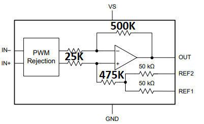
Question 4) We will ask you for reference. What is the resistance value of the differential amplifier circuit?

Best Regards,
Tom Liu

  • Hi Tom,

    1)     No

    2)     We currently don’t have a digital equivalent

    3)     Based on what I have seen, the answer is yes. But like you said, it is impossible to say so with high confidence. You would have to look at the Hall sensor spec and do a comparison. A step further is to look at the motor drive signal characteristics (frequency, duty, voltage) and find out what the accuracy requirements are.

    4)     The common mode input resistance is about 500KOhm, the differential input resistance is about 7KOhm.

    Regards, Guang

  • Hi Zhou,

    Thank you for your answer.

    There are 6 resistors in the internal circuit. My customer want to know the each resistance value about them.
    According to the [8.2 Functional Block Diagram] in datasheet, the tow connected to the REF1 and REF2 are all 50KOhm.
    Can you tell me the last four?

    Best Regards,
    Tom Liu

  • Hi Tom,

    The resistor values are approximately as shown in below figure.

    It should be noted that this block diagram is very simplified and many details are omitted. If customer is evaluating impact of external resistance on gain error, please read section 9.1.1.

    When not sure, please post questions here we’ll be happy to assist.

    Regards, Guang