This thread has been locked.

If you have a related question, please click the "Ask a related question" button in the top right corner. The newly created question will be automatically linked to this question.

OPA549: OPA549 Permanent Offset Error

Part Number: OPA549

Hi,

I try make a 60V 30A amplifier with OPA549. And I design first 5 OPA549 parallel and 1 different opamp for drive all of them. At the beggining, I do not get any problem and I used this system 1 day. After I chech all opamp one by one and I show one opmap begin 9V bias. for example I drive 1V but I show 10V, I drive -1V I show 8V. Also I drive AC signal and I show same offset. But when I use all of opamp I dont show bias.

After I change this opamp but at now the other one opamp show same error. I do not understand this.  Could some one help us?

Thanks

  • Hello Yakup,

    This level of offset change sounds serious. Would it be possible for you to provide the schematic for your OPA549 circuit, along with power supply, load and input and output signal information? Also, since the OPA549 devices are dissipating large amount of power I need to see the thermal arrangements you have provided such as heat-sinking, thermal connection method and device mounting information.

    Regards, Thomas

    Precision Amplifiers Applications Engineering

  • Hi Thomas,

    Thanks for your answer. I have one master opamp and 5 slave opamp(opa549). 5 slave opamp is parallel. I send my slave opamp schmatic and master opamp schmatic. In addition this schmatics I add 10uF and 100nF(parallel) slaveopamp's +Vs and -Vs. And I add  7,5R  33uF(series) output of slave opamps like snubber.

    Input voltage= +-6V(After master opamp -+30V) 

    Supply Voltage= +-30V

    Load= 0,6ohm coil

    For Thermal Dissipating I assambly all opamp cooler

    Thanks.

    Master Opamp Schmatics

    Slave Opamp Schmatics

  • Hello Yakup,

    I don't see anything incorrect about the master or slave Op amp circuits. However, there is one operating aspect of the circuit that is outside the normal linear operating range of the OPA549. 

    The input to the master amplifier is +/-6 V, which is increased to nearly +/-30 V at its output. The +/-30 V is applied to the OPA549 non-inverting inpuy which as a rated common-mode voltage (Vcm) range of about (V-) - 0.1 V on the low end, but about (V+) – 3 V to (V+) – 2.3 V on the high end. Since the slave OPA549 amplifiers are being powered by +/-30 V, a +/-30 V input exceeds the positive Vcm limit. Initially, the OPA549  may tolerate it, but I don't know if that is okay after hours. The ABSOLUTE MAXIMUM RATINGS Input Voltage Range is (V–) – 0.5V to (V+) + 0.5V so you are close. Note 1 under the table states "Exposure to absolute maximum conditions for extended periods may degrade device reliability."

    Exceeding the Vcm range severely degrades the dc and ac characteristics and possibly something is happening to the Op amp when operated in that non-linear input region.

    You responded "For Thermal Dissipating I assambly all opamp cooler." If you could provide more information about the assembly process such as how the OPA549 TO-220 package tabs get torqued down to the cooler and to what toque specification that is accomplished that would be helpful. It is possible to torgue the tab down with so much force that the amplifier die inside the package becomes physically and electrically damaged.

    Regards, Thomas

    Precision Amplifiers Applications Engineering

  • Hi Thomas,

    Thank a lot for your answer. Maybe my mistake this. After this I do not use 60V input. I hope I do not show this error again.

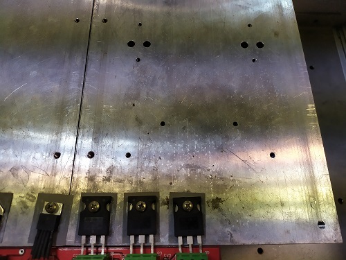
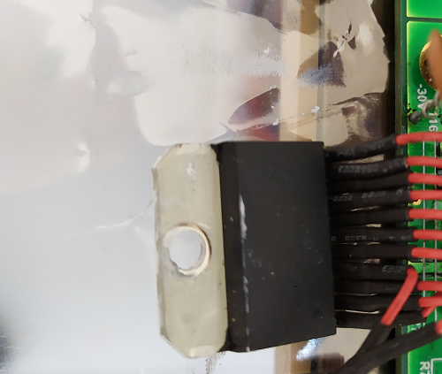
    I placed my opamp in cooler with screw. In picture 1 Its shown. In pıcture 1 is not opa549 but normaly I insert like this. Also I send my Opamp picture(picture 2).

    Thanks.

    Picture 1

     Picture 2

  • Hi Thomas,

    I remember somethink. After one opamp was demage. I change this opamp and I supply my system -+15V and I use 3 day. After I show same error different opamp. Maybe error is different.

    Thanks

  • Hello Yakup,

    Thank you for the information you have provided. Can you describe how you are controlling how much force is being used when fastening the TO-220 tab screw and nut to the heat sink? I am still concerned that if too much force is used the OPA549 die inside the package may be getting damaged.

    Thank you, Thomas

    Precision Amplifiers Applications Engineering

  • Hi Thomas,

    I place the TO220 tab surface exactly parallel to the heatsink and tighten the screw at the maximum rate. 

    Thanks.

  • Hello Yakup,

    The image you provided of the side-by-side OPA549 devices mounted across the sheet of aluminum is concerning. Is it a thin sheet of aluminum, or are there heat sink style cooling fins on the bottom of the sheet? Your application runs high current and I wonder just how hot the TO-220 packages are becoming in that physical arrangement. Do you have a thermal imaging camera or other way of capturing the temperature of the packages when the system has been up and running for some time?

    The OPA549 has built-in thermal shutdown and it can go into thermal oscillation if the package conditions become too hot. I do not know how long the Op amp can sustain continuous thermal oscillation and remain unaffected. It would seem that it should be able to withstand the condition for more than a day. Would it be possible for you to run a fan over the aluminum sheet to try and reduce the temperature of the OPA549 devices? If you find that the devices run okay over time without being damaged that would be a clue into the damage that is occurring.

    Additionally, I have been concerned about how the OPA549 TO-220 tabs are being secured to the heat sink surface and how much torque is being applied when the screws are tightened. I have attached a short guide that provides recommendations for installing the OPA549 to a heatsink. I mentions a #6 screw which I believe is based on an Imperial measurement size. A check on the web reveals that the closest metric screw size is 3.5 mm. That makes since because the hole in the OPA549 TO-220 tab is shown having a size from 3.76 to 3.86 mm.

    Regards, Thomas

    Precision Amplifiers Applications Engineering

    8664.OPA549 Mounting Recommendations.pdf

  • Hi Thomas,

    Thanks your answer. Our cooling system(aluminum)  has  heat sink style cooling fins on the bottom of the sheet and also we use fan to reduce aluminum temperature. I will try my system again paying attention your advice. After I write result in here.

    Thanks.

  • Hi Yakup,

    We haven't heard from you in a while, we hope your issue is resolved. I am going to close this thread now. Feel free to reply to to re-open if you have any questions moving forward.

    -Tamara