This thread has been locked.

If you have a related question, please click the "Ask a related question" button in the top right corner. The newly created question will be automatically linked to this question.

INA190: First stage stability issue

Part Number: INA190
Other Parts Discussed in Thread: INA199, TINA-TI

Hi guys

Our customer is using our INA190 as output current sense. 

Common mode voltage: 12Vout; Load Current: 0-50A.(DC output) Shunt resistor: 3* 0.3m ohm parallel;

Blue: Iout AC COUPLE; Yellow: INA190A3 OUT. 5A Iout

10A Iout

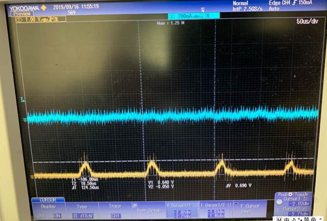
15A Iout.  You can see the red circle phonomenon. Oscillation problem

50A Iout;Oscillation problem

Schematic:

After that: we also asked customer to change R425 and R428 to 0 ohm. Remove the Offset_ADJ. But the results keep same.

However, when we replace it by INA199B3. The test result is OK. Please see the waveform: 

Pink INA199B3 OUTPUT


I found that INA199 has no the first stage but INA190 has one. why we have the first tage int the INA190? is this any relationship between both?

INA199 Block:

INA190:

Your feedback are very appreciated.

Thanks

-Pengfei

  • Hey Pengfei,

    Would you please explain why the load currents (CH4, blue waveform) look different between INA190 and INA199 tests?

    Does the INA190 ever track the load current aside from the output disturbances?

    Would you please share what the INA190 output pin is driving in the schematic?

    ---

    Overall you are correct to assume that this behavior could be due to the capacitive 1st stage of INA190. In the INA190 datasheet (section 8.1.3, page 23), it explains that harmonic current transients can cause periodic output disturbances in the INA190 due to the first stage's topology. The best and really only way to fix this is to attenuate the differential transients the INA190 is sensing. This is done by placing a capacitor (>5nF) across the inputs. Right now the customer only has a 100pF. If this doesn't attenuate the signal enough, then populate R425 and R428 with resistances > 10-Ohms. This should further drop the cutoff frequency of the input differential filter and thus further attenuate the current transients.

    Additionally, I should note that an output RC filter on the INA190 OUT pin can make the disturbance worse if the cut-off frequency is especially low. This is so because if there is an output disturbance, a large output cap would spread this energy out over time, thus lengthening the output disturbance.

    Hope this helps,

    Peter Iliya

  • Thanks Peter. For your question:

    1. At the two tests, the current load type is same DC Load. So the correct test should be the INA199. We also don't know  why the INA190 has these glitch or pump.

    2.I don't think the INA190 track the output current load. I think it is much different from the INA199.

    3. You can see below the output of INA190. The signal finally will go into MCU A/D port.

    We will have a try to adjust the inout cap and R425/R428. Do you have some simulation model to prove our INA190 is OK at this appliacation? And how much Input cap and Resistor we should use.

    Thanks

    -Pengfei

  • Hey Pengfei,

    Increase C422 to greater than or equal to 10nF as good starting point. Repeat the test with R425 and R428 as 0-Ohm and as 100-Ohm. You can increase these resistors up to 1kOhm with minimum effect on the DC accuracy to maximize the filtering of high frequency current noise. The only trade-off to decreasing fc of input filters is that it will slow down system current step responses, which might or might not be needed for this design. 

    We do have SPICE models for INA190 using the TINA-TI software. This model is a great tool to determine DC, transient, and output driving operation, as well as, determining system output stability (e.g., INA190 driving a capacitive load and how to compensate for this). I have included a simulation file that should represent customer's circuit to the best of my knowledge.INA190Schematic.tsc

    http://www.ti.com/product/INA190/toolssoftware

    http://www.ti.com/tool/TINA-TI

    Please note that the output disturbance behavior seen in this post is not modeled and cannot be debugged or analyzed using the SPICE model.

    Sincerely,

    Peter Iliya

  • Hi Peter

    Thanks for your share with this simulation. I simulated this module. I didn't see any difference between 100pF and 10nF input cap. But if we change the input resistor to 1k ohm. The output will become more smoth and no overshoot. So I think the input resistor may be the main role here. I will try it.

    And could you explain detailed about the first stage of the INA190? Why we add the first stage here? what application it target? what problem will it solve by using the first tage fiter inside of INA190?

    Thanks Again

    -Pengfei

  • Hey Pengfei,

    When actually testing hardware you will need the 10nF input cap. This cap will be more important than the input resistors since there seems to be high-frequency current transients in the real system. The TINA simulation is not simulating this and the INA190 model does not model its chopping behavior. Your conclusion that the input resistors are playing the main role here is potentially incorrect. Of course increasing the input resistors will lower the fc of the input filter and this helps attenuate noise better and smooths steps responses, but decreasing fc too much will slow down system response and may not be necessary as an input capacitor by itself may practically accomplish what is needed to fix the problem.

    This is why I said try testing hardware with just the input cap (10nF) first and if this does not work, then start increasing the input resistors.

    I cannot disclose the specifics about the first stage other than that it is extremely complex and there are switching capacitors and chopping circuitry to overall eliminate input voltage offset and input bias currents. The first stage's capacitors increases the differential impedance (~4.6MOhm) which lowers in the input bias current and thus allows to measure small currents in the micro-amps. This gives the INA190 very good DC accuracy and low power consumption.

    Best,

    Peter