This thread has been locked.

If you have a related question, please click the "Ask a related question" button in the top right corner. The newly created question will be automatically linked to this question.

TLV4111: Driving SAR ADC

Part Number: TLV4111
Other Parts Discussed in Thread: OPA388, OPA320, LM8272, LM8261, LM8262, LM7321

Hello,

        I'm working on a design to "digitize" an old analog vehicle sensor and running into some issues that I believe are tied to trying to drive the SAR ADC in the ECU.

The OEM sensor (see figure below) takes in +5V (provided by ECU) and runs that voltage through a fancy voltage divider and outputs a signal between 0.25V and 4.7V.  This output voltage is sent to the ECU which has some R's and C's before it hits the SAR ADC.

I started a design which gets rid of the analog voltage divider and replaces it with a custom CCA which at its heart is a ATMEGA328P Microcontroller.  The air flow sensor provides data to the microcontroller which I then use to tell how much voltage the DAC should output.  

Originally I had the output of the DAC connected straight to the ECU (i.e. no OpAMP) but during my design I took some amperage measurements on the OEM sensor and saw that the sensor to ECU line had as much as ~115mA on it.... Note that I don't have a ton of confidence in this number, we measured one car and the amperage was 30mA and then measured a second car and and got 115mA... I need to verify these measurements using better equipment but either way since the DAC is only able to output 25mA max, I decided I needed to buffer the output of the DAC.

After doing some research and speaking with TI support I decided to use the TLV4111, a main reason is that I wanted to ensure I could swing close to the rails (same voltage I'm powering the Op Amp with).  

I built the digital version both ways, with and without the Op Amp.  On the bench, I use a potentiometer to load the output and take voltage and amperage measurements to see how they perform.  As expected the one with the DAC starts to drop voltage well before 25mA while the design with the Op Amp can pull nearly 250mA before dropping voltage.

The interesting thing is that when these two devices were installed on a vehicle, it was the "no Op Amp" version that did better.  Unfortunately I wasn't present during the testing and don't have any voltage/current measurements but the vehicle without the Op Amp digital design was able to drive (still ran rough) while the Op Amp design was only able to idle and you couldn't even rev up the engine.

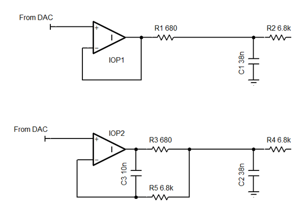
Since I was unable to get any measurements, I decided to get some more data on the ECU (which was unfortunately an unknown at the time) and took it apart to get some data.  It turns out the ADC in the ECU is a SAR ADC (Siemends 80C515) that has a 25 to 45pF capacitance.  There is a flywheel circuit in front of this ADC which consists of a 38nF cap and 6.8k Ohm resistor.   Thus I realized that I was greatly exceeding the capacitance load of the Op Amp (and DAC for that matter too) which is likely causing some instability issues for me.  You can see the circuits in the figures attached to this request.

My question is, what are my options here?  I looked at circuits to help keep the Op Amp stable, it seems the best one is to put a low value resistor on the output of the Op Amp but I can't do that because I'm trying to swing close to the rails.  I started to read about a snubber circuit but I'm not sure if that is suitable here either.  

  • Hello Peter,

    Interesting findings you received with and without the TLV4111 driving the ECU board. The impedance looking back from the flywheel circuit will be different when it is looking into the TLV4111 output, compared to when it is looking into the OEM sensor directly.

    In the case of the OEM sensor it appears to mostly be comprised of resistance, and some distributed reactance associated with the 5' wire. Alternately, the flywheel circuit sees the closed-loop output impedance (Zout) of the TLV4111, and whatever reactance there is associated withe the 5' wire. They most certainly represent different source impedances.

    Fortunately, the open-loop output impedance (Zo) of the TLV4111 is mostly a low resistance that remains flat across frequency. Those characteristics actually make it a more easily applied ADC driver than Op amps having high, wildly varying Zo that exhibit reactive regions. Therefore, I suspect the result you are obtaining is related to the RC component values currently being used in the flywheel circuit. If they are not carefully selected with regards to both the Op amp and the ADC characteristics, it is easy to end up with less than optimal performance from them.

    TI's Precision Labs series has a section devoted to A-to-D topics. The information was developed by TI's high performance ADC group. There is a section that covers the selection and optimization of the R and C values used in the RC filter, or flywheel circuit as it is sometimes referred to. Theselection  process is somewhat involved, but once correctly executed high levels of ADC performance should be achievable. You can find the TI Precision Lab for ADCs here:

    https://training.ti.com/ti-precision-labs-adcs

    Section 5, SAR ADC Input Driver Design should be of particular interest.

    Regards, Thomas

    Precision Amplifiers Applications Engineering

  • Peter,

    Was Thomas' answers sufficient or do you need more assistance?

  • It was helpful but I can't change the values in the ecu (I.e the flywheel circuit.)  I think I need to use an opamp that is better with handlinghigh capacitance.

  • Peter,

    Even high cap load drive op amps will have low phase margin with direct capacitance.

    Here are two ways to protect the op amp from the capacitive load.

  • Can you describe the benefits of one over the other?

  • Hello Peter,

    If you wish to evaluate a different op amp in the input circuit and see if that improves performance I suggest the OPA388. It has been applied successfully as a SAR ADC driver. It is available in the same style 8-pin package as the TLV4111. Here's a link to the datasheet:

    http://www.ti.com/lit/ds/symlink/opa388.pdf

    If your application can allow for a different package style, the OPA320 often provides very high performance in the SAR ADC driver role. However, in the case of the OPA388 or OPA320, the RC on the ecu board may not be optimum and their highest performance might not be fully realized. 

    http://www.ti.com/lit/ds/symlink/opa320.pdf

    Regards, Thomas

    Precision Amplifiers Applications Engineering

  • Peter,

    Regarding "Can you describe the benefits of one over the other?"

    Top one is low component count. Bottom one preserves DC voltage under a load. It compensates for I*R (voltage) loss in R3. Probably not important here because there is already 6.8K resistor in other side. 

  • Thanks for the data.  I was able to take new amperage measurements on the oem sensor for the output line, one feeding the adc and got 1mA max.  Looks like the inductive style current meter I was previously using was very inaccurate.

    That being the case, I no longer need the op amp to drive the large output current.  I'll look at the suggestions above. What do you think about the lm8272?

    With the much lower output current load are there better options?

  • Peter,

    Section 7.2 in the LM8272 goes into detail about how its design is tolerant to capacitive output loads.

    Other parts that that match the "unlimited cap*" search terms are LM8262, LM7321, and LM8261.


  • Hello Peter,

    We haven't heard from you in a while. We hope the issue was resolved. I am going to close this thread now. Please reply to re-open.

    -Tamara