This thread has been locked.

If you have a related question, please click the "Ask a related question" button in the top right corner. The newly created question will be automatically linked to this question.

OPA855: Anyone have experience importing SPICE file to RF CAD software, ie Genesys

Part Number: OPA855

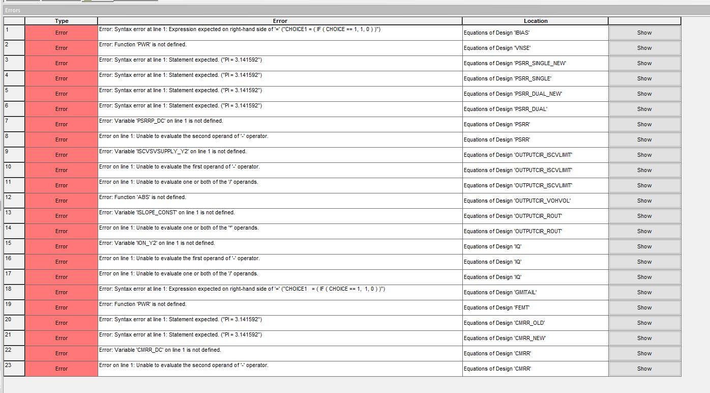
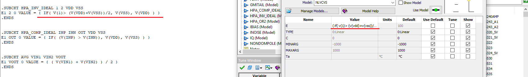
I am using the SPICE file for OPA855 and I am trying to import it into Genesys, which I've done, but now I'm faced with HOW to use this file within Genesys. Not sure if there are any other RF engineers out there who have done something similar, but would like to know. What I see when I import the SPICE file is I get a number of models that all seem to pertain to each of the subcircuit callouts in the SPICE file. What I'm trying to understand is how to use all that information to create a component with the same pinouts that are used when in TINA or other SPICE simulator. This way I can then use in Genesys to add in real resistors, caps, etc and PCB effects along with the OPA855 characteristics. Any help is appreciated.

  • Hello Michael,

         We are not familiar with Genesys and do not currently have the software; I have requested access to the software which might take a few days. In the meantime, I have linked two support threads from Keysight Technologies that may be helpful in solving your issue: Thread_1 and Thread_2. I will also leave a link to a video which could be helpful in downloading the correct files for successful import into other simulators: here. I would suggest posting a support thread on their technical support page. They are probably more familiar with the issue.

    Thank you,

    Sima Jalaleddine

  • Sima, thank you for your reply. While your response did not completely answer my issue, the Thread_2 link answered part of it. I think this SPICE file for the OPA855 is a little complicated as it has nested subcircuits and each subcircuit ends up being a separate model in Genesys. I have tech support at Keysight helping me, but put this out here just in case someone has done this here. From what I'm seeing it almost appears that one would have to build the model within Genesys from all of the subcircuits from bottom to top making all the appropriate connections. I'm hoping on the Keysight side they might have a faster way of doing that or some tool that can sort through the SPICE model and work that out similarly to what SPICE would do if you pull in a SPICE model and give it a symbol. Thank you for your help. If you have anything new to add or if anyone else has anything to add please do so.

  • Sima,

    I made some progress with my issue, however, I came across another issue. It appears that there is syntax that Genesys had issue with. Not sure why, but it pointed to one of the subcircuit definitions. I'm going to try and see if I can post that here for you to look at. The Genesys support person I am working with is not familiar with SPICE syntax so could not offer any assistance as to why there may be an issue. It appears that similar instances went through without a problem, unless of course this is a situation where I fix it here then it shows up again elsewhere.

    This is the error list I get in Genesys and it all seems to point to syntax errors. It could be issues using within Genesys, but there are examples of doing what I did to pull in SPICE files for components that work fine, so was wondering if it may be something unique to the OPA855 file. In any case if you have any insights would be helpful. Thank you.

  • Hello Michael,

         I was able to obtain the software, and I did run into the exact same issue as you where all the subcircuits within the OPA855 model were being displayed as separate models within Genesys. Would you be able to tell me how you were able to include all the subcircuits within one model?

         I also do get the exact error list as you displayed. I noticed that when we import the netlist within Genesys, it tries to parse each line within each subcircuit by placing the params within equations tab, the definitions (+) within the parameters tab, and the parts being used within the partlist. However, for some reason, it does not import these correctly. For example, I was able to fix some of the errors in the parameters tab by changing cmrr_dc to CMRR_DC for the CMRR subcircuit because the equation uses the variable in all caps rather than in lowercase. There are going to be more of these syntax errors showing up because once you fix the first line, it will detect a problem in the second line which would also need to be fixed.

          I will have to look into how to make this easier to fix, and will get back to you on an update. 

    Thank you,

    Sima 


  • SPICE to Genesys_191001.zip

    Sima,

    Please see the attached file. This is my Genesys workspace where I brought in the OPA855 model. What you have to do is within each subcircuit model copy the complete SPICE file for OPA855 into a Notes window. When you complete that you can create a symbol with the appropriate pins following the OPA855 model, which in this case is 6 pins as shown in the subcircuit. You'll need to save the symbol to a library, you can create your own. You can then pull the symbol into a schematic, open it, declare the OPA855 as the model to use and then set up a Linear Simulation. When I ran the simulation that's when I got all the errors. 

    Hope this helps.

    Sounds like though it is a SPICE code syntax vs Genesys syntax and may be just adjusting the SPICE code to make it run without error in Genesys. Seems like it would be a line by line review and correction. I'll let you TI people handle that so I don't mess up the model. Not that I would mess up your copy, but would mine which would leave me with erroneous results. If that is something you can do that would be very helpful. Thank you.

    Mike Ferrara

  • Sima,

    Just was curious how things are coming along. This is part of a small project I'm doing for a customer and would like to give them some feedback on progress and an estimate on when I can complete things which is dependent on this being done. Anything you can give would be helpful. Thank you.

    Mike Ferrara

  • Hello Mike,

         I was unsuccessful in finding a way to import the netlist without all the syntax errors. So it looks like we will have to do it the long way and fix all the errors manually. This seems to be an issue with Genesys not being able to read PSpice netlists; since, I also tried importing other PSpice netlists and led to the same results. I can help with these errors and give you what I have by tomorrow. Also, thank you for sharing the process on fixing the separated sub circuit problem.

    Sima 

  • Hello Mike,

        I did manage to fix all the syntax errors. If it does not run properly, I have a strong suspicion that Genesys could have skipped over some lines within the PSPICE netlist during the importing process. I have attached the updated workspace below, I hope it helps. 

    Thank you,

    Sima 

    8750.SPICE to Genesys_191001.zip

  • Sima,

    I got the following errors. Definitely not the same list as the others, but may reveal a missed error to fix. Looks like it might be calling out one error to fix which should cascade fixes to the other errors noted.

    Mike

  • Hello Mike,

        You are right that the one error is cascading into those consequent errors. It usually just means the program is showing you the list of steps it takes to abort the simulation due to the first error. However, I did some digging into the error, and it looks like for any source defined within a subcircuit (most commonly voltage-controlled voltage sources E and G), will produce the same error. Once you fix that error, you will get the same error for the other subcircuits with a voltage-controlled voltage source defined in a certain way. Fortunately, once you fix the error, it would be very easy to fix the other errors. The problem seems to be that Genesys does not like having input variables and if statements within the value portion of each voltage source. Most of the cases, the variables refer to the inputs defined for each subcircuit. Thus, if the input value changes, the value of the voltage controlled source would also change. Some cases the variable is within the equations list which is very easy to fix. I have fixed those and have attached the updated workspace below. However, since we have no experience with this software, we would not know how to fix these more complex errors targeted to having Genesys accept both if statements and input variables within the value portion of the sources. I would recommend asking the Genesys tech support. I have also attached an image to help with directing them towards the problem. 

    Thank you,

    Sima

    1205.8750.SPICE to Genesys_191001.zip

  • Sima,

    This is the reply from Keysight regarding Genesys and the OPA855 model.

    Hi Mike,

    Thank you for sending me the information from TI.

    The model described by TI is a dynamic model which its parameters change based on the simulation intermediate result.

    I am aware this issue. Unfortunately Genesys does not have this kind of capability to support this kind of model.

    ADS - another simulation tool from Keysight EESOF, has this ability.

    I am very sorry. Let me know if you want to consider to use ADS. I can try to arrange a trial version for it.

    Is it absolutely necessary for these areas to be "dynamic"? I have one other option I'm pursuing and that is to use ADS as they mention. I'm working on getting a trial version to help me through this part of the design. May need your help if I run into issues there.

  • Hello Mike,

       Yes, it is necessary for these sources to be dynamic in order for the model to function correctly. Hopefully, the ADS software will work better for these types of models.

    Thank you,

    Sima  

  • Hello Mike,

       I will be closing this thread. If you have any more questions or if you run into any issues with ADS please feel free to open up another thread, and I will be able to help you there.

    Thank you,

    Sima