This thread has been locked.

If you have a related question, please click the "Ask a related question" button in the top right corner. The newly created question will be automatically linked to this question.

THS3491DDAEVM: Modifying the Evaluation board

Part Number: THS3491DDAEVM

Hello everyone,

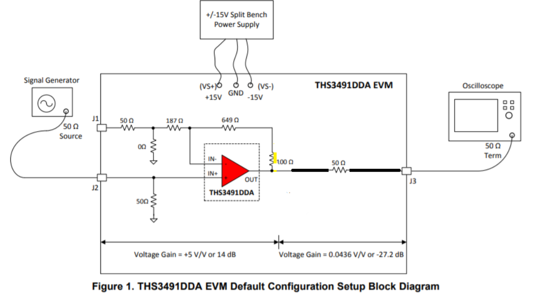
I recently purchased the THS3491DDA EVM, I tried testing it with the Signal Generator and Oscilloscope, as described in the picture below.

For my project, My test input range is 1VPP to 5VPP at 10 MHZ max, and have a smooth, no noise signal with a 5VPP to 25 VPP on output respectively. 

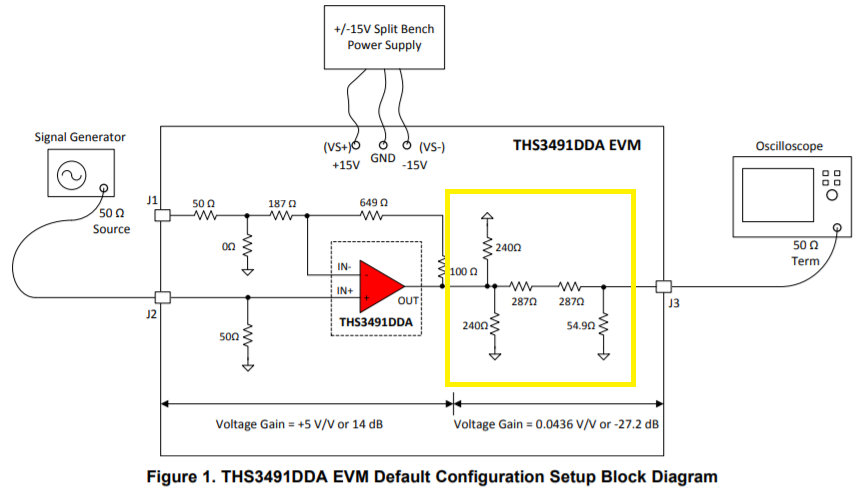
Suffice to say, I was not getting those results. I read the datasheet and it mentioned that the resistor network(Highlighted below) significantly decreases the gain. 

Is there a way to surpass that resistor network and what would need to be done to get the results I'm seeking above? Thanks. 

~Nate


  • Hello Nathan,

    Section 2.2 of the EVM mentions:

    "Remember, the output resistor network is only present to protect the measuring instrument from being over-driven by the device output for high-output signal swings. Desoldering the output matching resistor and replacing it with a single 50-Ω series output resistor that gives only 6-dB output voltage loss at the measuring instrument is easily done"

    Best,

    Hasan Babiker

  • Thanks for the quick response Hasan,

    I'm not quite sure What it means when it says "Desoldering the output matching resistor and replacing it with a 50 Ohm Series output"? 

    Also, could something like the following be done?

    Where all of the resistors can be removed and a connection, such as the one below, can be made?  

    Would the performance of the amplifier be affected in any way? Currently, the gain of the amplifier is 5 V/V. I'd like for it to maintain that gain and amplify my input signal without distortion.Thanks again.

  • Hello Nathan,

    What is meant by this is exactly as you highlighted in your diagram. The only difference would be that you would have a 50 ohm resistor where the black line is. The purpose of this 50-ohm resistor (and the one at the non-inverting input of the amplifier) is so that you can impedance match with 50-ohm matched equipment. Doing this will help with any reflection issues you might see in your measurements, however there will be 12dB loss as a result (6dB at the input and 6dB at the output).

    Otherwise, you can set the EVM in the configuration you showed (with the black line) and remove the 50 ohm resistor at the non-inverting input.    

    Best,

    Hasan Babiker

  • Thanks again Hasan,

    Just for clarification, would something like this suffice? 

    In total the Resistor at Non-Inverting Input and the Resistor network is removed. 

  • Hey Nathan,

    For a 10MHz signal that will work. If at some point you need to use the device at around 200MHz or greater, you will want to use the 50-ohm resistors for impedance matching. 

    Best,

    Hasan Babiker

  • Hello Nathan,

       This is a figure to accompany Hasan's response to indicate how to impedance match to a 50 Ohm source and measuring devices. 

    Thank you,

    Sima

  • Hello Hasan, yes 10MHz is basically the max I'm looking for my design. 

    I'll give it a shot and let you know how it goes. 

  • Hi Sima/Hasan,

    After doing some consulting, I was advised to not make the changes.

    Apparently, if the resistors are removed, it might significantly limit the amount of voltage supplied to the board. I.e. you wouldn't be able to supply +/- 15V as specified.

    The reasons were a bit unclear to me, so I wanted to hear from some experts as to why that might happen.  

    Thanks. 

  • Hey Nathan,

    I'm not entirely sure what it is you are referring to here. The resistors at the output of the amplifier shouldn't affect the voltages that are being supplied into the amplifier. Are you referring to the decrease in output swing because of a higher output current (as shown in figure 31)? This is only a concern if you are planning to still use the scope in a 50-ohm setting. I would recommend using a high-Z input impedance on the scope, and also making sure your signal generator is not expecting to see a 50-ohm load. 

    Best,

    Hasan Babiker

  • Hey Nathan,

    Were you able to get the EVM to work at your desired gain?

    Best,

    Hasan Babiker

  • Hey Nathan,

    I am closing this thread due to inactivity. If further support is needed please reply or start a new thread.

    Best,

    Hasan Babiker

  • Hello everyone, 

    sorry for the inactivity, I've been very busy. 

    I do appreciate the patience and the advice given.

    I have a couple more final questions before we can wrap this all up.

    1.) In the datasheet it says that replacing the resistor network with a 50 ohm series resistor will result in only a 6dB loss at the output. 

    If my math is correct, that would mean Voltage at output J3 would become: 0.5011 V/V x THS3491DDAout (V) as opposed to the 0.0436 V/V x THS3491DDAout (V) with resistor network? 

    2.) Is it possible to modify the board for a higher gain?

    For example, in the figure above, could you replace the 649 Ohm and 187 Ohm resistors with a 604 Ohm and a 78.7 Ohm respectively, to get a gain of 10 V/V? 

    1 + 704/78.7 = 9.95 V/V

    Could it be that simple or is the board specifically made for a gain of 5 V/V? 

    Thanks again! 

  • Hello Nathan,

    1) The 6dB loss is a result of the voltage divider of your 50 ohm series resistor and 50 ohm load. If your max frequency is still at 10MHz, you can use a high-Z load and avoid this loss in gain. 

    2) Yes, you can modify these resistors for a higher gain. However, please take note of the recommended resistor values in table 2 of the datasheet and try to stick to those values.

    Best,

    Hasan Babiker 

  • Thank you Hasan, that was very helpful.

    We can wrap this up.

    Take care! 

  • You can increase the gain, but that will not increase the maximum output swing. I saw 25Vpp early on. On +/-15V supplies, your max is probably 26Vpp or +/-6.5V at a matched 50ohm load at the scope - you can go to a lighter load at the scope keeping the 50ohm output R to isolate cable capacitance - might get some line bounce then, but your frequencies are low.