This thread has been locked.

If you have a related question, please click the "Ask a related question" button in the top right corner. The newly created question will be automatically linked to this question.

OPA858: floating nodes

Part Number: OPA858
Other Parts Discussed in Thread: TINA-TI

Hello,

I am trying to simulate my transimpedance circuit (the second amplification stage is not in the circuit yet) using the OPA858 

When trying to run it, it keeps showing following errors:

ERROR: Node U1:I0:I21:1:102 is floating and connected to current source G:U1:I0:I21:1:RA
ERROR: Node U1:I0:I19:1:102 is floating and connected to current source G:U1:I0:I19:1:RA
ERROR: Node U1:I0:I19:1:302 is floating and connected to current source G:U1:I0:I19:1:RC

u1:i0:vprobe1: Missing value, assumed 0V @ DC
u1:i0:vprobe2: Missing value, assumed 0V @ DC

What can I do about it?

Kind regards

  • Hello Sonja,

    Try adding a very large value resistors (>1Mohm) on the floating nodes so that there is a path to ground. You can change the temp of these resistors to -273.15 C to avoid generated noise from the components.

    Best,

    Hasan Babiker

  • Hello Sonja,

     To add to Hasan's response, you could add these large value resistors (>1Mohm) within the netlist of the model. An example of this was done and provided by Howard Bandell's latest response in a previous thread: https://e2e.ti.com/support/amplifiers/f/14/t/844373. It would be a similar concept with the OPA858.

    Thank you,

    Sima 

  • Hi Sonja,

    why not using TINA-TI?

    Kai

  • Hello all,

    thank you for answering!

    First I thought it would be too time consuming to get used to TINA-TI.

    But since Kai mentioned it again I tried it and it was ok. 

    And the OPAmp works there, no error messages :)

    (So I didn't try to modify the model in LTSpice yet)

    kind regards,

    Sonja

  • Hey Sonja,

    Glad you were able to simulate! Please let us know if any more problems arise.

    Best,

    Hasan Babiker

  • Hello,

    I am still having troubles simulating.

    Does anybody know why my circuit is not working as expected?

    I am expecting a linear output voltage, increasing with the input current.

    thanks in advance,

    kind regards

  • Hello Sonja,

        Would you be able to attach the Tina-Ti file? I believe the only difference is the resistor component. Attached below is my simulation result; the output voltage should increase with input current within the range of the amplifiers specified allowed output range. 

    Thank you,

    Sima

  • Hello Sima,

    thank you for that quick response! 

    I would expect a result like yours and don't know what I am doing wrong.

    Since it is my first time using Tina Ti, I am not sure about the settings I have to use.


    Here is my Tina TI file..

    Thank you,

    SonjaTina TI Test.TSC

  • Hello Sonja,

              I ran your file it seems to be working on my end. I clicked on Analysis, DC Analysis, DC Transfer Characteristic, and I tried to match your simulation time of 0 to 400u. This is my result: 

    I will attach the schematic, but I did not change any of the components:

    5706.Tina TI Test.TSC

    Thank you for trying to use Tina-Ti!

    Sima

  • Good morning Sima,

    there is something wrong or missing in my circuitry I guess.

    I am expecting a result like this (different OPAmp):

    Do you have any idea what it could be? 

    Is there something I don't get about the OPA858?

    Thank you,

    Sonja

  • Hello Sonja,

        I have simulated the OPA858 DC transfer characteristic from 0mA to 1mA which I have displayed below.      

         From this plot, the output voltage begins at around 1V with 0 to around 350 micro amps of input current. At 1mA of input current, the output voltage is at 3.16V (1mA*3.16KOhm) which matches the plot above. The reason it does not start at around 0V, as you have shown with a different amplifier, is due to the amplifier's output voltage limitations. Below, I have attached a snippet from the datasheet on the allowed range when using a +5V or +3.3V single voltage supply. From the OPA858 datasheet, the low output voltage typically starts at 1.05V and will start clipping at typically 4.1V for a 5V supply: 

    Let me know if you need further assistance with obtaining the same plot on Tina-Ti.

    Thank you!

    Sima

  • Hello Sima,

    thank you for answering my questions!

    I am still getting this simulation result:

    The simulation does not even finish at the right time.

    What am I doing wrong? Which parameters I am setting wrong?

    Did you make any changes to the circuit to get this DC transfer?

    Thank you,

    Sonja

  • Maybe there is something wrong with my OPA858 model?

  • Hello Sonja,

        I do not believe it is with the OPA858 model. Also, I did not make any changes to the circuit to get the DC transfer plot. Did you try using the file I sent earlier with the same schematic? I still believe there is something wrong with resistors in your Tina-TI program. I downloaded the file you sent me earlier, and the resistor component on my end looks different from the images you have been attaching. This leads me to believe that there are issues within your Tina-TI software. I would recommend uninstalling+reinstalling Tina-TI. If that does not work, I will move this thread to the Webbench Tools group. There, they are more knowledgeable on these types of issues in Tina-TI.

    Thank you,

    Sima 

  • Hello Sima,

    thank you for all the help from you!

    The different looks of the resistors is because I am using the European schematic symbol set and you are using the US one. So there shouldn't be a problem.

    However, since you mentioned to reinstall Tina TI, I did it and it worked! :D

    I am getting the same results as you now.

    Thank you very much!

    Sonja

  • Hello Sonja,

        I am glad it is working! If you have any other questions and concerns feel free to start a new thread.

    Thank you!

    Sima 

  • Hi Sonja,

    it's normal that a simulation can show weird results from time to time. Then it can help to redraw the circuit from scratch into a new file. So, it's not always necessary to reinstall the software. (By the way, I never had to do this.)

    Another trick is to change the component values a bit or to modify the settings of the signal source.

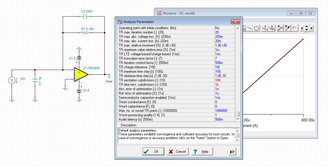
    Even the analysis parameters need to be optimized from time to time. If the edges of a square wave output signal look awkward, for instance, I use this modfication of analysis parameters:

    I find TINA-TI very useful: But, like any other simulation software, it's not always telling the truth...

    Kai