This thread has been locked.

If you have a related question, please click the "Ask a related question" button in the top right corner. The newly created question will be automatically linked to this question.

OPA549: negative part of the output is distorted

Part Number: OPA549
Other Parts Discussed in Thread: OPA541

Hi,

We have a customer with below concern:

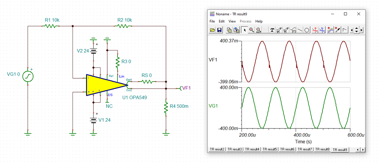
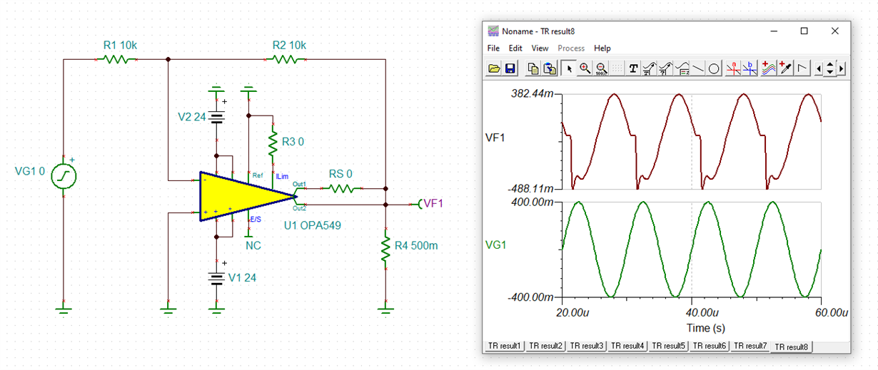
I use OPA549S and build an inverting operational amplifier with unity gain and the power supply voltages of +/- 24V, the input frequency is 100 KHz, the output waveform is normal when free of load, but when the load is 0.5ohm, the negative part of the output is seriously distorted please see the attachments, tell me how to solve it

sn_customerservice_case_7c7465091b528494d355ca217e4bcbce_attachments.zip

Regards,

Roland

  • Hi Roland,

    the simulation also shows the distortion when increasing the signal frequency. See the simulations at 1kHz, 10kHz and 100kHz:

    roland_opa549.TSC

    The OPA549 appears not to be fast enough for your application. Keep in mind that the unity gain frequency of OPA549 is only 900kHz.

    Kai

  • Hi Roland,

    This Op Amp can driver inductive load better than pure resistive load at 100kHz, like motor, for instance. What is your application? Perhaps we can find you an alternative  solution.

    Best,

    Raymond 

  • Hi Roland,

    I am going to close the inquiry. If you have any additional questions, please contact TI Precision Op Amp Application Team internally, if you'd like. 

    Best,

    Raymond

  • Hello Raymond,

    Apologies for the late response as I am getting feedback from our customer. Can you comment on below?

    2. could you introduce me some other power operational amplifier or power amplifier which can operate 100 KHz and provide the high AC current up to 8A or 10A. 

    (Roland: We have checked products in TI.com and we only found OPA541 to meet their current requirement. Do you have other solutions?)

    3. I wonder "The OPA549 appears not to be fast enough for your application. Keep in mind that the unity gain frequency of OPA549 is only 900kHz", the gain of the circuit is -1, the bandwidth should be 900KHz, why the distortion occurs when the operation frequency is 100 KHz even 10 KHz.  Also why the distortion occurs in the negative part only and the dV/dt in the distortion seems faster than the normal waveform.

    Regards,
    Roland

  • Hi Roland,

    a programmed gain of -1 means a noise gain of 2. So, at 100kHz the OPA549 has a gain reserve (loop gain) of only 14dB.

    Kai

  • Hi Roland,

    I did some pole and zero compensations on OPA549 circuit. It is not great, but it is able to get sine wave out, and able to driver 0.5 Ohm load. There is slightly attenuation at 100kHz, since the BW of the part is on the low side for the application. 

    If you still have any questions, you can reach me internally at TI. I am going to close this inquiry. 

    opa549 with 500mOhm resistive load 01212020.TSC

    Best,

    Raymond