A related question is a question created from another question. When the related question is created, it will be automatically linked to the original question.
If you have a related question, please click the "Ask a related question" button in the top right corner. The newly created question will be automatically linked to this question.
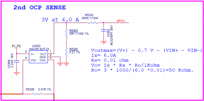
Thanks for reaching out on our forum. Can you clarify why your Ro in the schematic and the calculation do not match? Your Ro I assume is the output resistance, which you have ~30k in the schematic and 50k in the calculation.
As for the RC filter (50mohm and 270pf), I dont see any indication in the datasheet that it will cause instability. However, I will check with our design team.
Based on the values you provided, I calculate the filter cutoff frequency to be 1/(2*pi*0.05*(270pF))= 11.8Gohm. Whereas the INA169 has a cutoff at best for light loads is in the high Megaohm range. I expect your cap charge rate to have no issues keeping up with the INA169 for small signal. Are you intending to use this filter capacitor as a charge reservoir for a downstream ADC? While I check on possible stability issues with this device, you might want to sync up with the ADC team to make sure you design the proper charge bucket filter for the ADC.
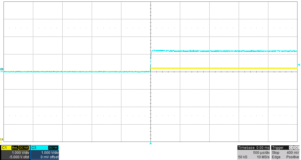
I did not get a clear response from design. So I went and ran some tests in the lab. At the moment I do not have INA169 parts on hand, but I do have INA168 parts which have the same architecture with different internal input resistance. For the first test I used a 30Kohm resistor in parallel with a 270pF cap to gnd. For the second test I used a larger cap with a value of 680pF. In each case I gave the INA168 a 200mV Vsense step, which equates to 1.2V. From these tests, I think the part will be stable. Yellow is VIN+ to gnd and Blue is Vout to gnd. One thing to note with the INA168 and INA169 is that these devices need a common mode greater than or equal to 2.7V.
I basically tested the circuit you provided, except I am using a INA168 which has internal 5k instead of a 1k. I also ignored the small resistances as their impact is likely negligible.. The traces themselves have resistance, although likely lower.
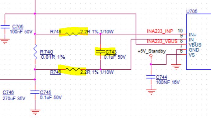
From your previous post I see that U705 corresponds to the INA233. As per the image found in the INA233 datasheet shown below, I dont think that will be a major issue.
An input filter to the INA169 should not make the part unstable. It may introduce some more error, but that as long as the resistance values are small (which your customer's resistors are as they are under 10 ohm) and the resistances have a small tolerance, the error should be small.