This thread has been locked.

If you have a related question, please click the "Ask a related question" button in the top right corner. The newly created question will be automatically linked to this question.

INA196A-Q1: How to monitor the correct current by UCD9090ARGZR

Part Number: INA196A-Q1
Other Parts Discussed in Thread: UCD9090A, INA293, INA196, UCD9090

Hi,

  In my design, I used INA196AIDBVR for current sense and UCD9090ARGZR for current monitor. The problem is:

1. I can't get the correct current value on the

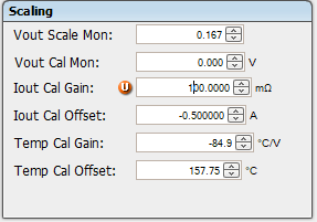
2. I tried to adjut the Iout gain and offset for UCD9090A via TI fusionDigital Power designer, then I could get almost correct current value on PCBA#1. When I applied the same Iout gain and offset on PCBA#2, the current vallue is not precise as PCBA#1.

3. How could I calibrate Iout gain and Iout offset so that I could apply those value in all PCBA and get the correct current value?

 UCD9090A . 

  • Hello Chien,

    Thanks for posting on the forum.  Please be aware that the input requires a voltage above 20mV to get a linear response.  There is a section in the datasheet that covers this.  See the section Accuracy Variations as a result of Vsense.  More in particular the section with 8.4.2.4 Low VSENSE Case 2: VSENSE < 20 mV, 0 V ≤ VCM ≤ VS as your VCM is equal to the VS.  

    The only way to calibrate and use is with the input being above 20mV differential across Vin+ and Vin-.  You could also look into the pin compatible INA293 the B pinout is the same as the INA196.  The specifications are not identical but some specifications are better  for the accuracy you are looking at and getting Vsense voltages below 20mV.  Some specifications that differ is the common mode range.  The INA293 is limited to -4V to 110V input common mode.

  • Hi Javier,

      Thanks for reply. I tried to set the input sense level above 20mV to get a linear response. But the result is not good as shown as below table. I used one Shunt Resistor and its value is 0.01ohm_0.5%.

  • Hello Chien,

    I cannot see a clear reason why you are getting such large errors.  Can you share the output voltage you are measuring?  Also how are you getting the output voltage of the INA196?  Is it from the ADC of the UCD9090?  If so can you measure with another option?  Have you verified that the INA196 give the same voltage output without the ADC connected to the output? It would be beneficial to measure the input differential voltage at the input of the INA196 in case the input voltage is incorrect.  This will help focus where the issue is.  Either at the input stage or the output side of the INA196.

    After looking at the schematic how do you limit the output of the INA196 to stay below the Absolute Maximum Ratings of the UCD9090?  I would recommend that V+ (Supply Voltage) be at the same supply of the UCD9090.  This will limit the output voltage of the INA196 and help prevent exceeding the Absolute Maximum Ratings of the UCD9090. 

    If the output of the INA196 improves when removing the UCD9090 from the output I would recommend placing an RC filter to the input of the UCD9090.  This will fix any loading issues from the ADC on the INA196.  This is a transient load that happens during sampling.

    Sorry for so much information I just don't want to give you only one thing to try.

  • Hi Javier,

      I found the root cause alreay. It's our layout isse. INA196 pin5 should be connected to shunt resistor, pin3 should be connected to power source. But those two pin in our desing are connect to the same net name. So the layout guy just connected the pin5 to power source, but pin3 connect to shunt resistor. After rework the PCBA, we could get the correct current value.

    Thank you for all suggestion.

    BR,

    Jonathan Huang