This thread has been locked.

If you have a related question, please click the "Ask a related question" button in the top right corner. The newly created question will be automatically linked to this question.

INA233: Ina233 reads current 4096 when load terminals are floating

Part Number: INA233

Hi Team,

I've a trouble with reading current at load terminals are floating. I getting correct value when use load or touch with multimeter probe.

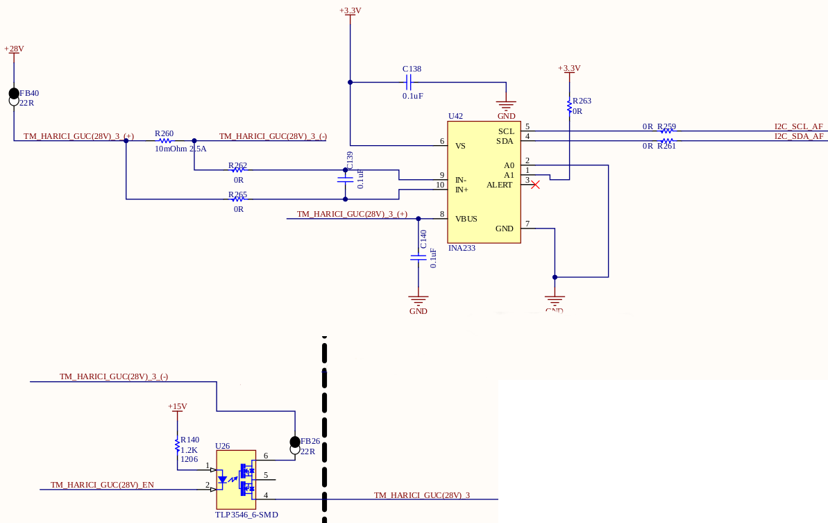
Note1:Vbus:28v, Config:High-Side Shunt, Shunt: 10mOhm

Note2:I use my own firmware and hardware, and I used before this hardware and software another projects, its worked correctly until last setup.

Do you have any idea why I having this problem.

Thanks for your suggestions.

Best regards.

Tarkan

  • Hello Tarkan,

    I'm not sure I follow your question. You are getting incorrect values when the inputs to the current sense amplifier are floating? In that case they may float to any voltage, typically driven by the input bias current.

    Can you please share a schematic of your system and more details of what you are measuring with a DMM vs. reading back in your software?

    Best regards,

    Ian Williams
    Applications Manager
    Current Sensing

  • Hi Ian,

    I waited for the new prototype, the problem still continues, I2C communication works correctly, I can write calibration data, read voltage etc.
    And I saw 2048 at the last test. If there is no quick solution I try to fix it with firmware.

    Note:4th pin of U26(optocoupler)  is load terminal.

  • Hi Tarkan,

    I also have problems to understand your problem. What I believe to have understood so far I would connect a dummy load from the

    TM_HARICI_GUC(28V)_3_(+) line to GND

    or from the

    TM_HARICI_GUC(28V)_3_(-) line to GND

    or from the

    TM_HARICI_GUC(28V)_3 line to GND.

    Don't know what your actual load is, but maybe a resistor with something between 100k and 1M will do.

    Kai

  • Hello Tarkan,

    We need you to provide a little more information to help you along.  From what I can gather, you do not have a communication problem, but you do have register with a value you do not expect.  You need to clarify which register you are reading that does not match expectation. For any measurement register, you will need to provide us with several other pieces of information.  For the READ_IN register, I need to know what value you wrote to the MFR_CALIBRATION register, I need to know you confirmed that value was written (reading back the register), and I need you to provide the value in the MFR_READ_VSHUNT.  By probing IN+ and IN- and reading the value in MFR_READ_VSHUNT, you should be able to determine if the device is damaged. If the MFR_READ_VSHUNT value matches an external meter reading, then you are likely doing something wrong with your current calculation.  Checking MFR_READ_VSHUNT should also quickly indicate if you have exceeded the shunt voltage input specification.

    If you are getting peculiar results in the READ_PIN, I need all the previously mentioned information as well as the value in the READ_VIN register.  You will need compare the READ_VIN value to what your multimeter reads from the device VBus and GND pins.  This also will indicate if the device is damaged. 

    For quick reference,

    Bus voltage (READ_VIN) LSB = 1.25mV

    Shunt Voltage ( MFR_READ_VSHUNT) LSB = 2.5uV

    If Read_VIN and and MFR_READ_VSHUNT are both accurate, then I will need know what Read_PIN is and what you think it should be.  This may help determine if you are missing a step in your post processing.