Hello,
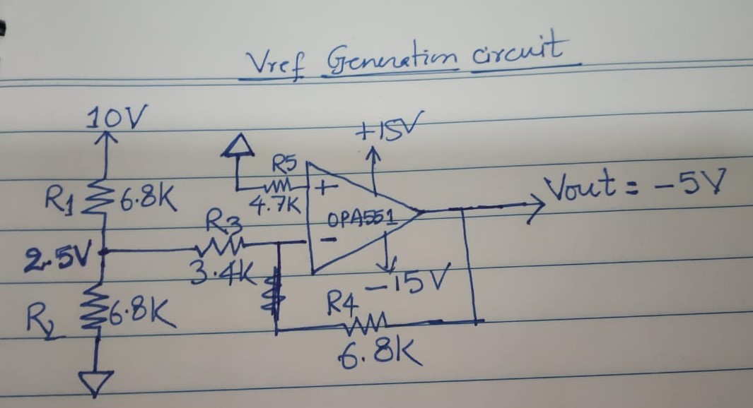
I am using OPa551UA in design as inverting amplifier with gain of 2.
Please see the below circuit:
The above circuit is realized on the board and voltage measured at the output of the OPA551 is -5V, but it is designed for -10V. Also voltage divider o/p is measured as 2.5V instead of expected 5V.
When I simulated the same circuit using PSpice, results are matching with the measured values.
Is it loading of of voltage divider circuit due to gain resistor network, R3 and R4. After removing R3, I get 5V at the o/p of divider network.
What is the output impedance of OPA551UA, not specified in the datasheet?
Could you comment on the behaviour of the above circuit. Why the opamp output is not -10V as expected?
Thanks & Regards,
Rajesh Kumar


