A related question is a question created from another question. When the related question is created, it will be automatically linked to the original question.
If you have a related question, please click the "Ask a related question" button in the top right corner. The newly created question will be automatically linked to this question.
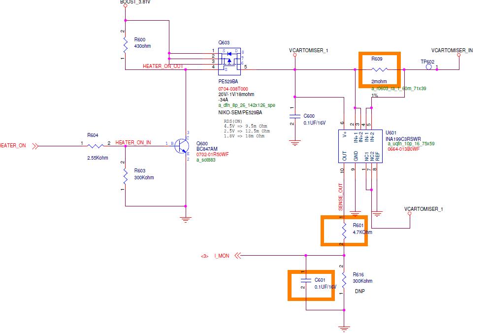
Thanks for reaching out on the forum. If your customer expects 20mA and they are measuring 300mA, that is unacceptable. To better assist you and figure out why their measurements are off I need the INA199 supply voltage, the shunt resistor value used, the common mode value at the INA199 input, the intended current measurement range, and the name of the ADC connected to the INA199. Everything but the ADC info is needed for calculating the various error contributions. The ADC may indicate whether the maximum capacitive load has been violated. I will also need to know the differential measurement between IN+ and IN- as well as the differential measurement between REF and OUT. These values should be collected directly at the INA199 pins if possible rather than at a test point, which may not be properly placed.
If you are unfamiliar with the various error sources in current monitor and would like to get familiar with them, I recommend watching our tutorial videos found here.
For 2.12A across a 2 mohm measured by a 200V/V gain INA199, I would expect 0.848V output. If I interpret you correctly, you're not measuring that number on your ADC. If you disconnect the ADC from the INA199 output and are able to measure 0.848V with a multimeter, then I think you might need to buffer the INA199 output for the ADC. If you disconnect the ADC and still cannot measure 0.848 from the INA199 output, then I would probe your V+ pin. It could be that your 3.81V boost is not adequately designed to supply 2A, so when that much current is sourced the INA199 supply might be drooping below the minimum operating voltage. Disconnect the ADC and probe the INA199 output and let me know what you observe.
Patrick meant the supply voltage of INA199. What is the supply voltage during the measurement? Is it dropping down unwantedly?
To find the mistake, divide and conquer :-)
For further testing I would disconnect the ADC from the INA199. I would remove Q603 and connect a stable and robust +5V voltage source to the terminal "VCARTOMISER_1". This +5V voltage source must be able to drive a current of 3A. Then, I would connect a dummy load from "VCARTOMISER_IN" to signal ground. This dummy load can be a simple but precise power resistor.
If everyting is ok up to this moment, I would add the customers parts, piece for piece, one after the other. Begin to replace the +5V source with the "BOOST_3.81V". Then add Q3. Then add the customers load. And so on...
Our EVMs designs are verified before we put them out for distribution. If you are getting a inaccurate measurement on that, then either you do not have a stable supply within specifications for the part, your resistance from the INA199 output to ground is really low, INA199 ground and system ground potential are very different, your measurement equipment has an issue, or you damaged the part.
I think what Kai has posted should help you along. However, if you still run into issues, here are steps to rule out each of these items I mentioned above.
Checking the equipment.
- Measure the Vsense voltage with a DMM for 1A. Does your DMM read 0.002V? If it does not your load source or DMM has an issue.
- If you are automating measurements with labview or something similar, you need to make sure you give your DMM adequate sampling time for the specified resolution, otherwise you could measure less than what is expected.
Checking the ground potential.
- Do a continuity test between INA199 gnd pin and your preferred system ground test point. If it fails, you may have a bad solder connection somewhere. I would also check the resistance too. I have seen meters that buzz even if the resistance is a few ohms. The closer the resistance to zero the better.
Checking the Ref potential
- Your schematic indicates it should be connected to ground, so I would verify at the pins the potential is the same. If not you might have a bad solder connection somewhere
Check the supply
- After verifying a good ground connection. Measure the supply for various load conditions and verify that the supply does not move and is within specification. If the supply moves alot when you ramp up vsense, your supply is not stable enough and you might need a larger decoupling cap to maintain the supply level. If the supply is not within spec, your supply may have reached the compliance limit. For bench supplies, this should be possible to adjust. For a board level supply, you might need to do some redesign to ensure it can supply the proper amount of current for the desired supply voltage.
Check the quiescent current
- As long as you do not have a small resistor from the INA199 output to ground, the quiescent current should be sub mA. Check this current with nothing connected to the INA199 output. If you see a quiescent current above 100uA, then your device may have been damaged.