This thread has been locked.

If you have a related question, please click the "Ask a related question" button in the top right corner. The newly created question will be automatically linked to this question.

INA226: INA226

Part Number: INA226

Hi there!

First of all, i have to say tha is my first time with this awesome current sense amps, i used to go on classic amps everytime I need to measure current.

So, I've chosen de INA226 and saw all videos about this in training.ti (amazing channel too).

But i've been facing some troubles to chose the corret Rshunt applying the formulas and using the error analysis.

I read that for the best accuracy I should use the max Vsense value of 81.92mV. The Input current range is 1 to 12 mAmps, and applying the formula (82mV/8mA) the result is around 10 ohms.

When I put 10mOhm in error analysis, the error is very high (>10%) and the best value using error analysis is 100mOhm.

My application is to measure low current (2 to 10mAmps) through a laser diode (OPV302) and the i2c s almost mandatory.

  • Hi Paulo,

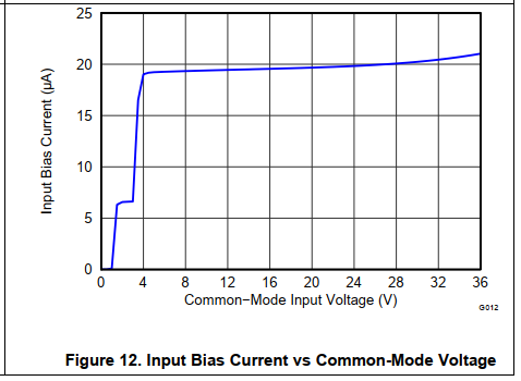
    a measuring current of 1...12mA might be a bit too small for the INA226 because the INA226 shows an input bias current of 10µA typical. But also look at figure 12 and 13 of datasheet to see how the input bias current additionally varies with the common mode input voltage and temperature.

    Kai

  • Hello Paulo,

    The issue must be that the error calculator on the product page only works with shunt resistance less than or equal to 100 mOhm. This is why the reported error is so large. We apologize for the inconvenience.

    A quick way around this is to scale the shunt and current values. So set shunt to 60 mOhm and the current range from 100mA to 1.2A. This results in input sense voltages of 6mV to 72mV, the same sense voltages if the shunt was 6Ω and currents were 1mA to 12mA. I chose 6Ω as the shunt resistor because the exact resistor to achieve full scale range is 81.92mV/12mA = 6.82Ω; however, I am unsure about the availability of resistor with values close to this so I rounded down to whole number.

    Doing this will account for all error sources except that of input bias current (IB). The offset due to IB (Vos_IB) is dependent upon the input common mode voltage (VCM) and is equal to Rshunt*IB-.

    Hope this helps.

    Best,

    Peter Iliya

  • Hi Peter.

    Thanks for helping.

    I was thinking about what just said.

    And if I use 6mOhm resistor, i'll have this:

    Iload = 8mAmps

    Vshunt = Rshunt * Iload -> 0.006 * 0.008 = 48uV.

    Error [%] = Vos / Vshunt - > 10u / 48uV -> 20.84%.

    If i'm right, the best way to solve this is finding a opamp with lower Vos, isn't it?

    I dont know if TI has something like this and I2C, maybe i'll have to choose amp + interface..

    Can You help me??

  • Thanks Kai!

    You've helped me a lot.

  • Hey Paulo,

    Unless there is some power dissipation requirement, there is no reason to use a 6-mΩ resistor for your application. You will want a 6-Ω shunt resistor to maximize the shunt voltage and minimize offset error. So with a 6-Ω shunt for currents ranging from 1 mA to 12 mA, the shunt/sense voltage will range from 6 mV to 72 mV. 

    The INA226 (and all basically most other amplifiers) will exhibit the largest error at the minimum signal voltage. So the max error just due to offset alone is 100*10µV/6mV = 0.167%.

    The error tool online limits the shunt resistor to 100mΩ for no real reason, other than to limit IB error. We apologize for this if it has cause confusion.Now there will be additional offset errors from CMR, PSR, and IB. The IB won't be accounted for in the online calculator given the limitation of Rshunt.

    So if in your application the VCM=12V, then IB = 10uA going into each pin. If the device is measuring positive Vsense, then IB- will flow across the shunt resistor creating a voltage offset. So Vos_IB = 10µA*6Ω = 60µV. This is significant offset, but may not break any error requirements you have. Continuing along with the 6-Ω shunt example, this means the total max offset (Vos_max) equals 10µV+60µV = 70µV. This will increase error to 70uV/6mV = 1.167%.

    If this breaks the error requirement, you could either decrease the shunt resistor to reduce Vos_IB or you could add another 6-Ω resistor in series with the IN+ pin. This will create another offset in the opposite direction which should theoretically cancel out the Vos_IB error. See the simulation below:

    INA226example.TSC

    Best,

    Peter

  • Oh Peter, I'm really sorry about de R value.

    I read 6mOhm instead of 6ohm in your text.

    Now I understand what you said!

    Thanks again!!!

  • Hi Paulo,

    and the use of microcontroller offers you the possibility to calibrate out all the errors caused by input offset voltage and the input bias currents, at least in a first order approximation. This will allow you to furtherly improve the accuracy of your measurement.

    What common mode voltge do you expect? Is it a high side or low side current measurement? See again figure 12 of datasheet:

    Kai

  • Hi Kai! Thanks again...

    Yes, I dont think we're facing some accuracy issues anymore.

    About de the measurement, high or low side, i'm studying wich one is better. As I said before, I've never used opamps for current measurements.

    The voltage will be something about 12V - Vlaser (2.2V@7mA), about 9.8V.


  • Hi Paulo,

    yes, I agree. A common mode voltage of 9.8V would result in a nearly contant input bias current, as can be seen from figure 12 above.

    Good luck,

    Kai

  • Hey kai klaas69 (5218539)!

    I'm not totally understanding the main difference between use high or low side measurement. I unsterstood the circuit connections, but no the advantages and disadvantages..

    Can You help me?

  • Hi Paulo,

    the advantage of the low side current measurement is that you are not plagued with high common mode voltages. So, you can use a simple OPAmp circuit or at least a "One OPAmp differential amplifier" circuit to amplify the voltage drop across the shunt. In any case the remaining common mode voltage is rather small and can easily be handled by the OPAmp circuit.

    The high side current measurement has the disadvantage that you have to handle large common mode voltages which can be decades higher than the voltage drop across the shunt. In this case you need an amplifier with extreme high common mode rejection ratio. In this situation you would choose one of the TI's INAs specially designed for high side current measurement.

    Kai

  • Hi Kai, understood!

    Thanks again.