This thread has been locked.

If you have a related question, please click the "Ask a related question" button in the top right corner. The newly created question will be automatically linked to this question.

LM358: Grounding issue on my rectifier design

Part Number: LM358

Hello 

I'm trying to implement a rectifier and AC voltage sensor. The rectifier part works just fine. I'm able to power my device without any issues.

Please look at C2 in the screenshot (Circuit schematic). This connector is connected to AC voltages. Vin is a rectifier and the DC part is to power the device. AC-1 to AC-5 are AC voltages that are sensed at ADC-0 to ADC-4 respectively. AC-6 is the neutral line of all the AC voltages connected to the board.

When AC (1-5) are connected to AC voltage, the device works just fine. No issues at all. But when AC-1 and AC-2 are connected to 120 VaAC while AC (3,4 and 5) are not connected to anything, ADC-0 and ADC-1 read the right value but ADC (2,3 & 4) read 7.5V while they should read 0 V.

I connected all the -ve terminals of the bridge rectifiers to have a common ground but when there is no AC voltage, the respective +ve terminals of the bridge rectifiers reads 58V (+ve is floating while -ve is grounded). Is there any way to fix this? cause my ADC is reading the incorrect value of 7.5V when it should read 0 V.

I was told to use an isolated amplifier with unity gain. Unless there's isn't a better solution, Can I use the following Opamp with unity gain to accomplish this:

https://www.digikey.com/product-detail/en/texas-instruments/LM358P/296-1395-5-ND/277042

If not do I have to use a specific isolated opamp like the following:

https://www.digikey.com/product-detail/en/texas-instruments/AMC1100DWVR/296-46067-2-ND/6571602

Thank you 

  • Hello User,

    The common neutral line does make it through the rectifier from that AC input to the + output even if the other AC input is open (not connected). This happens because your common ground is 'hot'

    If the common ground was the common neutral (AC6) instead and use a single diode (anode to AC IN and cathode to each resistor divider output) to get positive half of AC input then unconnected channels would be zero. The downside is that you are only looking at the input positive half of the waveform. This may be good enough.

    Alternatively you could lose the 5 input common grounds and measure the difference voltage between + and - for each of the five channels.

  • Hello Ron, 

    Thank you so much for your response. I considered half-wave rectification but had 2 issues. The capacitor needs to hold the voltage longer than before (twice as long). I could get by this issue, but I was told that isolation is necessary from the AC line. Since the isolation amplifier is mandatory, I thought I go with full-wave rectifications. I'm not pulling any current. It's just to read the voltage via ADC. If isolation is optional, then I could go with half-wave rectification. I agree that it's good enough (no isolation though). 

    All those AC lines are coming from the same module. They all have a common neutral line. I can't change this. 

    Thank you 

    Varun R

  • Varun,

    What is the goal of the circuit. What part of the AC voltage do you need, average, peak, RMS (hardest), instantaneous value?

    Where does the output go (to other circuits that can share a potentially 'hot' ground or not)?

    If the output goes to something external or to a person then isolation from neutral and line will be required.

  • Hello Ron, 

    The goal of the circuit is to read the voltage in the line via the ADC's of my IoT device. This device is powered via the top part of the circuit and consumes 0.3-0.4 at 12V. Whenever the ADC's change by more than 10 V, I programmed it to send data via its modem to our a could server. 

    The +ve of the device is connected to the +ve of the bridge rectifier while the -ve is connected to the -ve of the bridge rectifier. That's why I had to connect all the -ve's of the bridge rectifiers to have a common ground for the device. 

    There is a module that is powered by the AC mains voltage. The 5 AC lines which go to the ADC come from different parts in the module. They turn OFF and ON depending on various scenarios which is what I'm trying to monitor using this board. Then this board is connected to the IoT device (Which I think is external relative to the board). So I'm guessing isolation is necessary?

  • Varun,

    Would it be good enough to digitally detect (on or off) for the 5 AC lines. That could be done with a simple optocoupler that includes isolation and won't need external power.


  • Hello, 

    I thought about that. But my boss told me that it won't work. Hence I have to do it the hard way. Since you asked me this, I'm assuming I definitely need isolation. 

    I already have a few LM358 opamps with me to test. I could buy this one: https://www.digikey.com/product-detail/en/texas-instruments/TL074BCDR/296-14999-1-ND/562659

    It has 4 channels. I will use a combination of LM358 and TL074 to isolation all the AC inputs. I'll first perform half-wave rectification, then reduce the voltage via a voltage divider, then pass the voltage to the opamp. 

    I'll simulate it this weekend and share the results. Please let me know if I'm on the right track. 

    Thank you 

    Varun R 

  • Varun,

    The half wave rectification and reduction sounds good. The GND point will be AC6 (common neutral). 

  • Hello 

    Just to be clear, there is no isolation required?

    I simulated the circuit in Tina with an opamp and got the result I wanted. I can power the opamp using the output of the transformer which itself has isolation. I have attached the circuit and simulation results to this message. 

    If you think the opamp is not necessary, let me know. I'll get rid of it. 

    Thank you 

    Varun R 

  • Varun,

    Isolation will be needed. The neutral AC line ground must be treated as if it was hot.

    If you want average line voltage at a gain of 1/10 (for sine waves) then this would work. 120VAC in is 12VDC out

    HW1.TSC

    You also should distribute the line voltage across multiple resistors to lower the voltage each resistor has to endure. This lowers power dissipation and voltage modulation.

  • Hello Ron, 

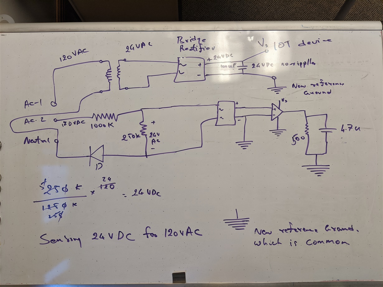
    I ran into a problem when I practically implemented the circuit. I don't have any DC voltage here. The challenge is to power the opamp. I didn't think this would be a problem because, in my first schematic that I shared here, I have a rectifier that is working great. I thought I could power the opamp from this rectifier.   

    However, there is a grounding issue. The opamp power supply is to the ground of the bridge rectifier which is isolated from the AC mains by a step-down transformer. When I implemented the circuit using 24V DC, the opamp is not giving the voltage sensed by the voltage on its + pin. 

    In order for this circuit to work in the real world, I should get rid of the opamp. Or find a different way to isolate the circuit. I have attached the full simulation schematic to this message. 

    Please let me know if I missed something. 

    Varun Rfullwaverectifier.TSC

  • Varun,

    Your image and attached TSC file are different. I added a line isolated (transformer) power source to my circuit.

    HW2.TSC

    You still need to decide where to add line isolation for the signals. You mentioned IOT, is this a stand alone Wifi application? 

  • Hello Ron, 

    There is a grounding issue which I didn't see before. Hence the difference. In the simulation, we have one common ground. No issues here. 

    However when I implemented the circuit, I dint use 4 diodes. I used a bridge rectifier https://www.onsemi.com/pub/Collateral/MDB8S-D.PDF

    It has 4 pins, 2 for AC lines(Live and neutral), and 2 for DC out(+ve and -ve). Post rectification, all the voltages are referred to the -ve of the bridge rectifier. Not the neutral of the AC (like the simulation). I'm don't think it is right to connect the -ve of the bridge to one of the AC inputs. 

    When I power the opamp from the rectifier voltage, its referred to the -ve of the bridge rectifier. The opamp output is with reference to its ground which is the

    -ve of the bridge. Opamps input is referenced to the neutral of the AC input. Hence the opamp is not showing any voltage at its output. That's the problem here. 

    Can I just get rid of the opamp and read the voltage after half-wave rectification (no isolation)? I will further increase the resistance in the circuit to pull current in micro amperes and have an appropriate fuse for safety?  


    What do you think?

    Varun R

  • Varun,

    The op amp is just a buffer , many ADC can read output without the buffer. 

  • Hello Ron, 

    There is a grounding issue with half-wave rectification Ron. the ADC of the device reads voltage with respect to its ground which is the -ve of the bridge rectifier. So I will have to connected the -ve of the bridge rectifier to the neutral line which ruins my isolation ground which I created using a transformer. 

    I have to use the same bridge rectifier and connect all the -ve terminals together to have a common reference ground. However, when the AC input floats, I end up getting 7V instead of the expected 0V. I can fix this in the device by setting the ADC offset. This will work for my application. 

    My question now is, Is it safe to do so?

    How about I put a diode on the neutral line to the bridge rectifier? When the AC floats, the neutral is not connected to the respective bridge. Hence will end up getting 0 V?

    I have attached the schematic to this message. 

  • Varun,

    We are not making good progress at the moment. It is a good time to review the main goal. As I understand it, the goal was read 5 AC line voltages and report that to "IOT device" with isolation in the middle. 

    The key aspect is the isolation. There are two obvious choices here, 5 channel of isolation (seem bulky and expensive) or 1 channel (that carries 5 pieces of information).

    Does your "IOT" device support I2C or some other "smart" serial data stream?

  • Hello Ron

    Yes, the goal is to read AC voltages in the 5 lines which have a common neutral via 5 ADC"s of the device. Therefore all the AC reading much be in reference to the ground of the device which is the negative of the bridge rectifier. 

    I know we didn't make any progress but I went the wrong way with half-wave rectification. There is no common ground with half-wave rectification. My original design is the way to go. It has a common ground. There is only one problem. When one of the AC's floats, I'm getting 7V across because the neutral is not floating as you said. 

    What if I use a diode to block the neutral and connect it to the bridge rectifier? And I'll connect all the -ve of the bridge rectifier to the ground of the device. This should work right?

    Else I could use a pull-down resistor at the AC inputs. I will use 1G ohm as it will have 120V across it when the line doesn't float. 

    Your questions:

    Are you suggesting a MUX, to implement 1 channel? I won't be able to switch MUX select lines that fast. There will be a delay by the time I get the reading. 

    It just has UART apart from ADC's. 

    Thank you 

  • Varun,

    The only logical choice for a common ground (on the hot side of the isolator) is the common neutral line. Anywhere else is going to cause problems. I didn't see read time lag as a problem because earlier versions had 4.7k resistors and 100uF caps which is a half a second time constant.  

    For isolator, I recommended ISO224 which accepts a +/-12V input so a simple resistor divider could scale down the 120VAC line in real time (the whole sine). No bridge rectifiers are needed for the measured lines. Once the signal is on the isolated side you can tie to the IOT ground safely.

    IOS224 is not one on the products that I support, so start a new post refreing this thread. The ISO engineers will be able to help you with the ISO244 design.

  • Hello Ron, 

    I agree ground has been an issue here. ISO224 is a great product. It provides much-needed isolation and I can get rid of the bridge rectifier and opamp. Isolation is not just for safety here but it also provided a common ground between IoT device and rectifier ADC.

    I'll design the circuit with ISO224 and post a new thread to get a second opinion. Thank you so much for your help. I really appreciate it. 

    Have a great day!

    Varun R