This thread has been locked.

If you have a related question, please click the "Ask a related question" button in the top right corner. The newly created question will be automatically linked to this question.

Ringing in the RF circuit

Other Parts Discussed in Thread: OPA694, OPA2695

Hi, I'm building a simple pre-amp but with pretty high BW, ~ 200MHz. Part of the circuit is pretty simple and shown here:

I'm trying to get the noise down. My SPICE shows about 0.5mVrms. I put in a 150ohm to shun the imput to measure the noise.

The problem I have here is that, sometime, I get about 500uVrms noise at the output which is consistent with the simulation. But a lot of times, I'm getting some kind of ringing with an amplitude of about 3mVrms to 5mVrms. The waveform of the ringing looks like this:

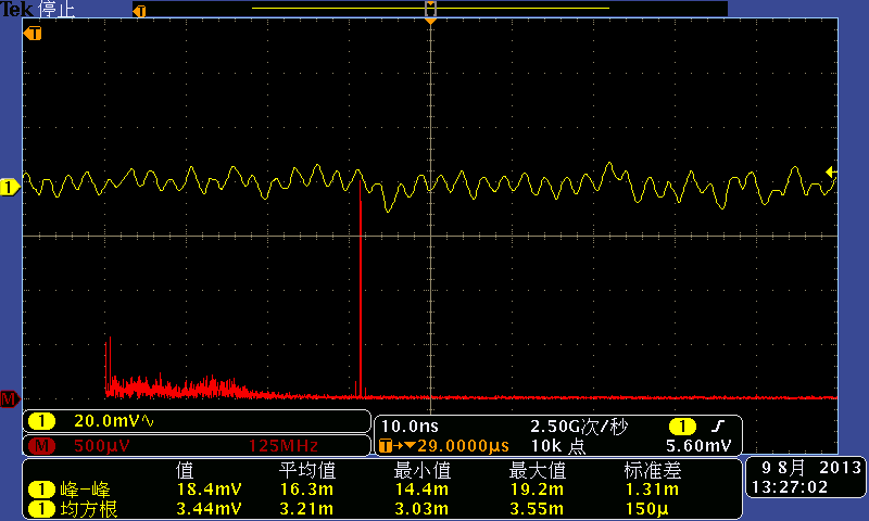
The frequency of the ringing is about 400MHz.

My questions are, 1) is it the ringing from amplifier instability; 2) what's the recommendation to get rid of it?

Many thanks in advance,

Jay

  • Hello Jay,

    I don't see any obvious cause of instability in this portion of the circuit. 

    It would be good to probe all of the amplifier input pins to make sure the DC bias points are at the correct voltage. What sort of diode is D3? Are the non inverting inputs biased to ~0.6V?  What is the purpose of diode D3? 

    Where does the input signal come into this stage? 

  • Hi Loren,

    The DC bias points were all good. The purpose of DC is to provide a bias of 0.6V for some specific purpose by the client.

    The input is from another differential amplifier. It is replaced with a 150 ohm resistor (R15).

    What kind of characteristics is in the output? If it does not look like a ringing from instability, what is it?

    Thanks a lot,

    Jay

  • Hi, I'm still not able to get the circuit right. The ringing is still the main issue. I'd like to get some more basic education on this.

    Below is an output from new circuit we built, same shematic. We were very careful this time with the PCB layout, for example, making sure the the ground plane is cut out under the input pins, etc. We don't have big ringing, but still has the small ringing which degenerate the SNR. We should get more than 10x better SNR if the ringing is suppressed.

    So the basic questions are, is this a typical ringing or oscillation from an unstable circuit? What's the difference between the small amplitude oscillation and a full amplitude oscillation (like 2Vpp when the circuit is really bad) as far as the op amp stability is concerned? Is it due to layout or due to the op amp?

    Thanks,

    Jay

  • To add on to my previous questions, with regarding to the waveform which has two distinct frequencies of 400 MHz and 12 MHz, assuming the instability is caused by the poles in the transfer function, can we infer that the frequencies of the oscillations are to the frequencies of the poles?

    Thanks,

    Jay

  • Hi,

    Any TI guru watching this? I need help. Is there anyway we can get dedicated help like before?

    Thanks,

    Jay

  • Hello Jay,

    For the OPA694 (current feedback type), your feedback resistor (R23 + R25= 250ohm) seems too low. According to OPA694 Figure 39 (Feedback resistor vs. Noise Gain), you may want to raise the feedback to ~420ohm (Noise Gain = 2V/V in your case) to see if your instability is affected by it?

    Regards,

    Hooman

  • Hi, thanks for the quick reply. I'm glad you guys are still monitoring this. Actually we just updated the feedback resistors according to the datasheet. But the ringing is still there.

    I'd most like to know, based on experience, if there is anything we can learn from the output ringing waveform that I posted. Like, if the oscillation is due to the feedback resistance, or parasitic capacitance, or impedance mismatch (reflection), or some kind of coupling? Does the frequencies, one low and one high, will tell us anything?

    Yes, I'm asking about the experience. I'd like to know, if an experience engineer might also got the same initial problem and how he/she would start out to solve this problem.

    Thanks,

    Jay

  • Hello,

    To answer your question: I personally cannot base much on the 2-tone oscillation waveform you've posted. Other more experienced people reading this might be able to and they can comment.

    BTW, I cannot find any information on OPA2698 in your schematic. Is that the correct part number?

    Regards,

    Hooman

  • Hi Hooman,

    My bad. It should be OPA2695.

    I still think the two tone oscillation should mean something. I hope it is one of a typical problem for the RF circuit if not careful. It must have a reason.

    Thanks,

    Jay

  • Hello Jay,

    I looked in the OPA2695 datasheet and with a 402 Ohm feedback resistor and a gain of 1 there is about 4dB of peaking in this configuration.  It is possible that the extra noise you see at 400 MHz is not instability, but rather gained up noise. 

    If you increase the feed back resistor to about 800 Ohms it may reduce the high frequency gain peaking.  The screen shot is not conclusive on a root cause. 

    One thing to keep in mind is that there can be ambient RF that is gained up by your test circuit.  Are you able to use a spectrum analyzer to make sure that there is no 12MHz or 400 MHz energy in the lab?

    Another thing that would help to debug the circuit is the board layout.  Have you followed all of the suggestions in the datasheet as far as board layout.  Extra capacitance on the device I/O pins can cause problems.    

  • Hello Jay,

    "I still think the two tone oscillation should mean something. I hope it is one of a typical problem for the RF circuit if not careful. It must have a reason."

    The frequency signature of the noise is certainly important, but it can still be pretty hard to find the root cause. 

    Is the frequency very stable?  Does it change with temperature?  Does it change if you place your finger in different portions of the circuit?  Have you tried probing the circuit with a high impedance, low capacitance probe? 

  • Hello All,

    In addition to Loren's comments:


    I also suggest you try and narrow down the source of the ringing / instability to either one of the two OPA2695 stages, or to the OPA694. You could probe each output (with the front end disengaged from the other (open R11 and R12)) to see if you can pin-point the origin of the ringing. Note that with oscillations, it is possible to pick up the ringing at one point while the origin is somewhere else (through ground bounce, radiation). So, you must be careful when probing to not be fooled.

    In addition, using the scope probe tip (or your body through a sharp point like a conducting tweezers tip)  to touch different nodes of the circuit (while monitoring the ringing waveform), often offers clues as to which node is most sensitive to this probing. This includes the supply and ground nodes next to the devices. This may allow you to hone in on the circuit area responsible.

    Regards,

    Hooman

  • I also suggest you try and narrow down the source of the ringing / instability to either one of the two OPA2695 stages, or to the OPA694. You could probe each output (with the front end disengaged from the other (open R11 and R12)) to see if you can pin-point the origin of the ringing. Note that with oscillations, it is possible to pick up the ringing at one point while the origin is somewhere else (through ground bounce, radiation). So, you must be careful when probing to not be fooled.

    "

    Yes, we did that. If we disengage the last two stages, all were stable.

    In addition, using the scope probe tip (or your body through a sharp point like a conducting tweezers tip)  to touch different nodes of the circuit (while monitoring the ringing waveform), often offers clues as to which node is most sensitive to this probing. This includes the supply and ground nodes next to the devices. This may allow you to hone in on the circuit area responsible.

    "

    This was very interesting, I found, when I use my Tek probe on the output pin #6 on the OPA694, the oscillation got really big and fully grown. But the input pins were not very sensitive to it. If I put the probe on the minus input pin #2, the ringing actually diminished a bit. So this was strange and made me think maybe this had something to do with driving a capacitive load? But, when I separated the two stages (mentioned above), the #6 pin was not sensitive to touching anymore. So now it did not sound like a capacitive load issue anymore.

    Any thoughts on this? Please also see my other repplies.

    Thanks,

    Jay

  • Hi Loren,

    The frequency was fairly stable. It changes a bit when I changed the resistors, but I'm not sure if it was related to the resistor values or some other parameters like the temporation.

    I don't have a low cap active probe. I'm thinking of buying one, like a Tek TAP1500. But I'm not sure if I know enough to take advantage of the new probe. It's kind of expensive. I don't what it would tell me. Isn't the high freq oscillation appears everywhere and it would be hard to tell which is the origin?

    Thanks,

    Jay

  • Hi Loren,

    I ended up changing the R_f on the OPA694. It was 402 when we had the ringing. But when we changed the R_f to 500 that seem to have eliminated the ringing, see the waveform below:

    So it is gone now! But we are going to look deeper. For example, based on the previous waveform with the oscillation, if we ignore the ringing, it looks like the signal fluctuation should be about 10mV_pp. But now I get 38mV_pp. Why?

    And why increasing the R_f above the recommended value, see figure below, would eliminate the ringing?

    Thanks again for all the help,

    Jay

  • With current feedback amplifiers you have the ability to change the loop gain by changing the value of RF.  THis is a very powerful tool in adapting the amplifier for a given specific circuit.   It is comparable to putting a capacitor in the feedback loop of a voltage feedback amplifier. 

    The suggested Rf charts are made for ideal conditions with purely resistive loads on a very sparse circuit board. It is not uncommon to use larger values of RF than called for in the datasheet.

    In the scope trace above it looks like noise with a very small bump in the FFT.  If the "ringing" circuit had a failry high Q it would have suppressed the broadband noise.  With the ringing gone it's possible you're seeing the truse noise floor.  The bump in the FFT is not large enough to contribute much, so it's likely that the noise is due to other circuit elements.   What frequency range does the scope FFT represent? 

    Also, the inverting input gain with respect to the 150 Ohm input shunt resistor is 5.36, so you've got some noise gain with respect to the inverting inputs. 

    I'm also not sure how well the noise from the diode and the 1k resistor on the non inverting inputs is being bypassed by C6 and C8.  Check the datasheet on those capacitors and see how effective they are over the amplifier bandwidth.   Both low frequency and high frequency noise could be getting to the amp inputs. 

  • Hi Loren,

    The FFT range is from 0 to 1250MHz with 125MHz for each division. 

    Here is a waveform/FFT plot of the output when the 2nd stage is disengaged:

    You can see the RMS is about 1.9mV. So it looks like the noise in the complete circuit is from the 1st stage.

    Also, there is a bump in the FFT. This is the circuit with R_f = 402. Sorry, for some reason I did not the one for the R_f = 500. I will make up for that.

    How do we calculate the noise due to the resistors and C6 & C8? I guess we will just run the TINA to figure out.

    Thanks,

    Jay

  • Hello Jay,

    Here is what I'd to find out if your 1st stage is working well and does not have any gain peaking (which could be the cause of the excess noise you are measuring presumably at the output of OPA2695 (shown as OPA2693 in your schematic) at either U1B or U1A):

    Lift up the input end of R7 and R9 and tie them to a bench Generator with 50ohm shunt to ground at the junction. Run step response and / or frequency response test to make sure the response does not suffer from excess overshoot / peaking.

    BTW, if you are suspecting any input noise, you could just monitor the output while shorting C6 / C8 to ground to eliminate any noise injection from them. If the output noise does not change when you do so, then these are not adding any noise.

    Regards,

    Hooman

  • Hi Hooman and all,

    Haven't done much in the last few days and also will be out of office for two weeks. Will report back either good or bad in a few weeks.

    Thanks all,

    Jay