This thread has been locked.

If you have a related question, please click the "Ask a related question" button in the top right corner. The newly created question will be automatically linked to this question.

Urgent: LMH7322 Schematic Check

Other Parts Discussed in Thread: LMH7322, TINA-TI

Hello Team,

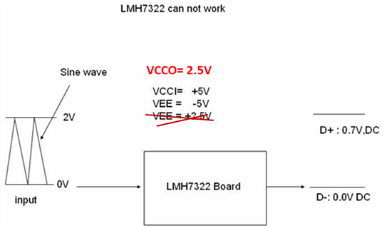
Need you support to check if the schematics has wrong connections. The customer, zeroplus, test the circuit but it cannot work.

Could you kindly check attached schematics for the customer? 

2022.lmh7322.pdf

I'd appreciate your reply!

Thank you!

Regards,

Ting

  • Hi Ting,

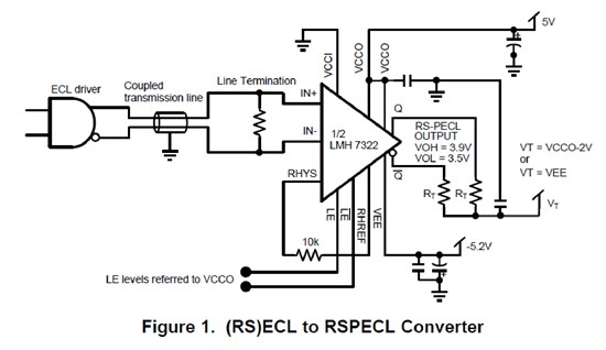
    I'm not sure if the application has the output pull-down resistors (RT in Figure 1) or not, since you have not shown them?

    The LMH7322 output will not toggle if those resistors are missing. See Figure 18 for the equivalent output schematic that shows the emitter output and the need for the RT resistors.

    Also, you have labeled VEE as "-5V" and also as "+2.5V"! Needs correction. I think you meant VCCO= +2.5V but I'm not sure?

    Your diagram is also not clear what the other input is set to? May be 1V (to detect a 0-2V input)?


    Regards,

    Hooman

  • Hello Hooman,

    Sorry for the typo. They should be VCCO= +2.5V, VEE=-5V, VCCI=+5V.

    As for RT, they are 82-ohm as attahced if below pdf.

    5582.LMH7322-Zeroplus.pdf

    The other input is connect to a voltage divider and adjust by VR.


    Sorry for the uncleared information in last question.

    In the customer's schematics, could you comment on that if things need to change?


    Thank you!

    Regards,

    Ting


  • Hello Ting,

    I cannot figure out why the LMH7322 output is not toggling in your pdf schematic!

    Here are some comments anyways:

    1. Make sure the 0-2V sine wave is at the device pin 8 (and not JP1-2, for example) by using a scope on this pin

    2. Double check the voltage on the reference input (pin 7) to make sure it is somewhere in the range of voltages you read on pin 8

    3. Disconnect any load connected to the output pins (through JP2) for testing purposes (to make sure the output load is not preventing toggle)

    4. Go around the device pins with a scope and ensure all the power and ground and other pin potentials

    5. In case the device has been damaged, try another fresh LMH7322


    Regards,

    Hooman

  • Hello again,

    Couple of other notes I like to add:

    1. The DAP (metal area under the device) should be tied to the VEE potential (not ground), as noted in datasheet Table 2. It can also be left floating (if heat dissipation is not a concern). Double check.

    2. Do you have power supply current readings (VCCI and VCCO, and VEE) to share so that we can sanity check them?


    Regads,

    Hooman

  • Hello Hooman,

    Thank you so much for the supports!

    The customer's problem is solved by re-check each pin and solder them again.


    Thank you for the debugging steps!

    Regards,

    Ting

  • Dear Hooman,

    In this customer case, input signal (IN+) is from 0V to 2.0V. (IN-) might be 1.0V. Output signal is LVDS.
    So I can understand why VCCI=5V and VCCO=2.5V.
    But I wonder why VEE="-5V".
    I think in this case, VEE can be set to 0V.

    I am planing to use this IC. So I want to know whether VEE can be set to 0V in such case.

    Thank you and best regards,

    Yoshida
  • Hi Yoshida,
    You can operate the LMH7322 with the conditions you've noted (VEE= 0V, VCCI= 5V, VCCO= 2.5V).
    On the output, if you plan to tie the RT resistors to ground too, choose RT= 86ohm (2 places) for about 14mA average current.

    Regards,
    Hooman
  • Dear Hooman,

    Thank you very much for your quick response.

    RT=82ohm is very valuable information for me. I have not noticed it.

    Thank you so much.

    Best Regards,

  • Hi, I am a little late to the party on this thread, but I am hoping you can help me!

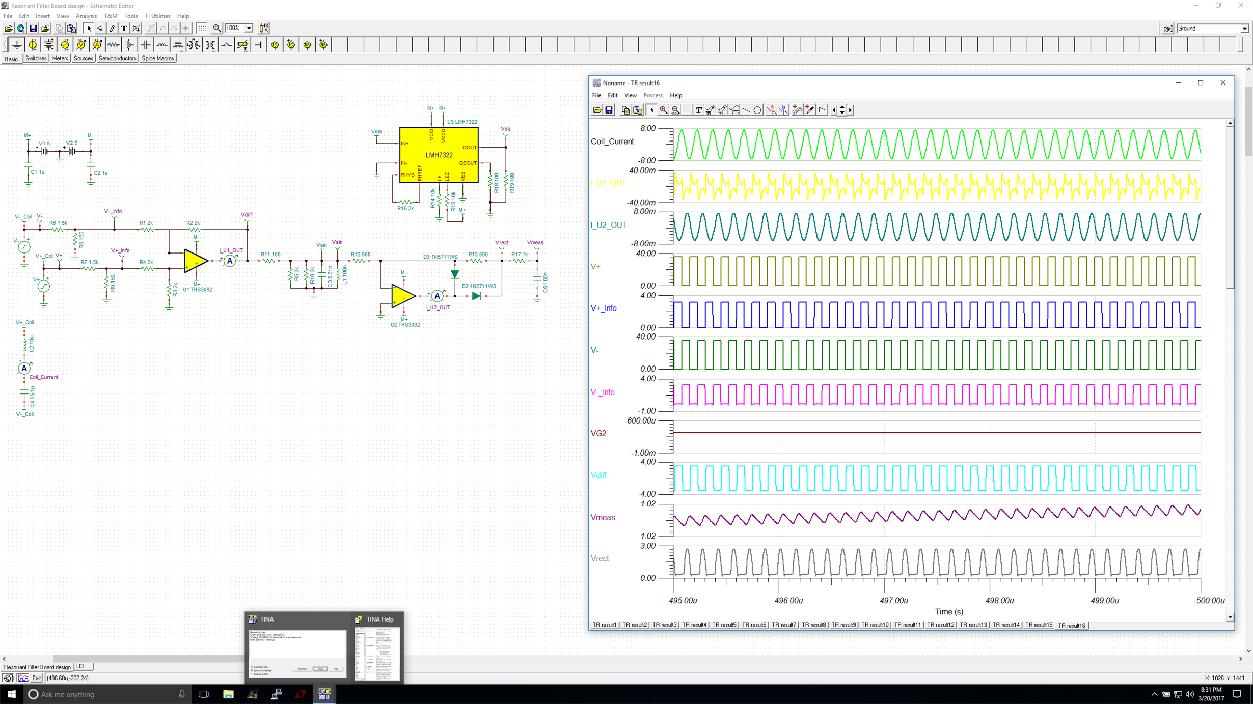
    I am trying to use this part in simulation (TINA-TI) and in real life and I am struggling quite a bit.

    My VCCI=VCCO = +5V

    VEE = GND

    RT = 100Ohm

    I have attached a simulation file (I know this is a long shot given this post was from over 2 years ago, but maybe you'll see it!) Can you help me figure out what I have done wrong? Idk how familiar you are with TINA-TI, so I will attach a screen shot too. 

    Any and all help is appreciated!! 

     Resonant Filter Board design.TSC