This thread has been locked.

If you have a related question, please click the "Ask a related question" button in the top right corner. The newly created question will be automatically linked to this question.

OPA690 Asymmetrical Power Supplies

Other Parts Discussed in Thread: OPA690

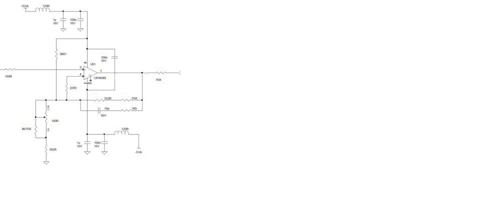
Hoping you can confirm this application.  Looking to power an OPA690 from +3.3V and -3.0V power supplies.  The application is a low speed cable driver where the high output drive and disable features are important.  

The amp is configured as a unity gain voltage follower with the + input DC coupled to the signal source.  The input signal is a 5KHz digital signal swinging from 0v to +3.3v.   TINA simulations all look fine.    Do you see any issues that may not have been reflected in the TINA model?

4064.ltc_tx_cct_design 3V3 op amp.TSC

  • Hello,

       I would not recommend using the OPA690 this way. You are violating 2 conditions for operating this amplifier in a linear region:

    1. According to the Datasheet, on Page 3, the Common Mode Range of the amplifer on +/-5V supplies is +/-3.5V. What this means is that the input voltage to the amplifier at the non-inverting and inverting pins should be 1.5V away from the supply rails in order to operate the amplifier in the linear region. In your case of +3.3 & -3V supplies the range is +1.8V and -1.5V. You are violating this condition on the high side.

    2. According to the Datasheet, on Page 4, the Output Swing of the amplifer on +/-5V supplies is +/-4.0V. What this means is that the output voltage of the amplifier should be 1.0V away from the supply rails in order to operate the amplifier in the linear region. In your case of +3.3 & -3V supplies the range is +2.3V and -2.0V. Again, you are violating this condition on the high side.

    The problem with your current simulation is you are not using the correct probes to monitor the output voltage. Please see attached simplified schematic to see an accurate simulation of the output.

    4520.Circuit Design.TSC


    Regards

  • Hi,

    Thanks for the information.

    If I drop the input voltage swing to 1.8V will this be OK? My output voltage should preferably have a swing of 1-2V pk to pk. A unity gain setup would work for me. 

    Thanks


    Chris

  • Chris,

      Dropping to 1.8V should work.

    Samir

  • Samir,

      I am using a similar circuit with +-5V supplies.  I do not see any requirement for power supply sequencing.  If the -5V supply is applied first, before the +5V supply, is there any issue?  Any long-term reliability degradation?   I would not think so, just want to verify, please.

    ~Leonard

  • Leonard,

    You should be fine. Just ensure that you are not violating any over-current condition during startup. The ESDs can safely handle around 10 mA of current for brief periods without causing long-term damage.

    -Samir

  • Thanks Samir,
    I'm not seeing where any overcurrent condition would come into play. Do you see a possibility of an overcurrent situation?
  • Hi Leonard, I cannot see anything directly, however with power supply sequencing I don't know what voltage is on each node and what is being driven by the previous stage, so its just a cautionary statement to ensure nothing untoward from the previous or subsequent stages.
    -Samir