This thread has been locked.

If you have a related question, please click the "Ask a related question" button in the top right corner. The newly created question will be automatically linked to this question.

Noise in transimpedance circuit using LMP7717

Other Parts Discussed in Thread: LMP7717, LMH6601, OPA656

Hello,

For our laser communication project, we use your LMP7717 amplifier to detect a very low current modulation (@ 1MHz) received by an avalanche photodiode (by using a transimpedance circuit in Fig. 1 below, RF and CF are chosen to have ~ 2MHz bandwidth).

Fig. 1. Transimpedance circuit using LMP7717, RF = 47 kΩ, CF = 2 pF

We have a probleme in noise level of the output voltage.

The measured noise level of this circuit is about 0.56 mVrms (for the 2 MHz bandwidth, Fig. 2 and Fig.  3). Fig. 3 shows the variations with frequency of 2 – 3 MHz in time domain.

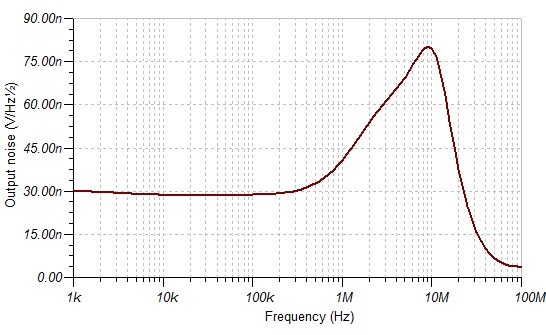
But by using the current and voltage noise level of 0.01 pA/Hz1/2 and 5.8 nV/Hz1/2, the theoretical calculation of output voltage noise [1] gives us a noise level of 0.11 mVrms (for the 2 MHz bandwidth). This theoretical noise level is 5 times smaller than the measured noise level.

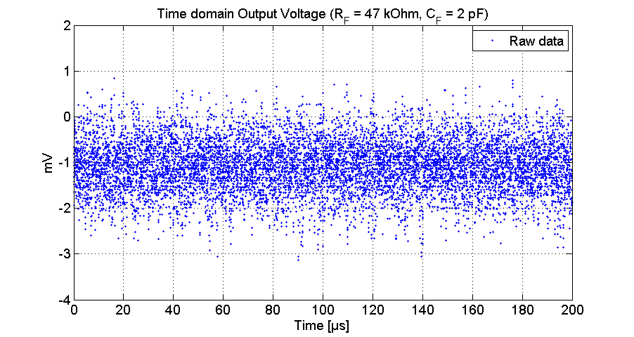
Fig. 2. Time domain Output voltage noise [200 µs, Fs = 50 MHz]

Fig. 3. Time domain Output voltage noise [4 µs, Fs = 2.5 GHz]

Fig. 4. FFT of output voltage (for the raw data in Fig. 2)

In the noise spectrum (Fig. 4, FFT of the raw data in Fig. 2), there is a bump around 2 MHz and it dominates the noise level. The bump also appears when we use RF = 100 kΩ, CF = 0.68 pF (proposed in the LMP7717 datasheet).

So, we would like to know:

  • Why do we have a bump of 2 MHz in the noise spectrum?
  • How to optimize the noise level of the transimpedance circuit (BW ≥ 1MHz) using LMP7717?
  • Have you a testing circuit for LMP7717?


[1] - Texas Instrument, “Transimpedance considerations for High-Speed Amplifier”, Application Report, SBOA122, Nov 2009

Thank you in advance,


PHUNG Duy-Hà

  • Hello Phung,

    How are you making the measurements? Is it with an Oscilloscope or do you have an ADC that is digitizing the output? can you make the measurements with a Spectrum Analyzer?

    1. What is parasitic capacitance of the photo-diode?

    2. Please confirm if the load capacitance really 22uF? That seems excessive.

    3. Have you tried making the measurements with common-mode closer to mid-supply? Change R3 and R4 to be of equal value. If possible make these resistors small (<500Ohms) so that the noise contribution from the resistors is small.

    Samir.

  • Hello Samir,

    Thank for your response,

    The measurement is made by an Oscilloscope.

    1. The capacitance of the photodiode is 4.1 pF

    2. The capacitance 22 µF is not the load capacitance, it is a coupling capacitance between the amplifier output and the SMA connector which is connected to the oscilloscope.

    3. We have just measured the noise level with mid-supply common-mode, R3 = R4 = 100 kOhm,  the bump around 2 MHz in the noise spectrum is decreased by a factor 3. The noise level in this mode is about 0.5 mVrms (@ BW = 2 MHz), 12% smaller than 0.56 mVrms measured with the circuit in Fig. 1.
    We will add a low pass filter and see the variation of noise level.

    PHUNG Duy-Hà

  • Hello Phung,

     I ran a simulation of the ac response with 22uF cap, and I see a 9dB peaking in the ac response. This is usually an indicator of instability and oscillation. Removing the cap. from the circuit and resimulating results in no peaking. I think you need to find a way to isolate the output of the amp from the load capacitance. Please see attached response and the TINA circuit.

     In case you are unaware you can download TINA spice from the TI website and run some simulations to fine-tune your circuit.

    8422.LMP7717_TIA.TSC


    Samir.

  • Hi Samir

    Thank you so much for the simulation,

    In fact, we have removed the 22µF capa for the DC detection.

    By using your simulation file (22µF removed, in mid-supply common-mode),there is a bump around 10 MHz in the noise density spectral curve shown in Fig. 5 below.


    Fig. 5. Simulation of noise spectral density

    In our measurement, we have also a bump around 2-3 MHz. So I think that the bumps in spectrum is normal.

    We have added also a low pass filter (BW ~ 3.5 MHz), and the noise lever is decreased by a factor 1.6.

    The noise level measured is about of 0.35 mVrms (BW ~ 3.5 MHz), still 3 times greater than the theoretical noise level (Fig. 6), but we approach the theoretical noise. Thank you very much!!!


    Fig. 6. Simulation of the total noise level at Output


    PHUNG

  • Hello Phung,

    After a little more investigation I think I understand why your measured results are worse than the simulated results. The LMP7717 is a decompensated amplifier which means it is not unity gain stable. This means that there is a 2nd pole in the Aol curve (Fig. 36 of datasheet) before the unity gain frequency. Usually there are effects around this 2nd pole which are not always well modeled in the simulator. This could very well be why the simulated and measured results do not match.

    Samir

  • Hi Samir,

    Thank you so much for your explanation.

    So, the 2nd pole before the unity gain frequency increases high frequency noises (from 300kHz to 20 MHz) at the output voltage, cf Fig. 5.

    For our application, we need to detect a current of 0.3 µA at 2 MHz bandwidth, the transimpedance circuit using LMP7717 is not ideal for us (it increases noises from 300 kHz to 2 MHz at the output signal). So, can you suggest us another low noise amplifier with high bandwidth and no pole around 2 MHz?

    Thank you in advance,

    PHUNG

  • Hello Phung,

     If you can work with +/-5V supplies OPA656 is a very good amplifier. Also, you can try the LMH6601 and see if it meets your needs

    http://www.ti.com/lit/ds/symlink/lmh6601.pdf

    Samir