This thread has been locked.

If you have a related question, please click the "Ask a related question" button in the top right corner. The newly created question will be automatically linked to this question.

LMH6574 Mux expansion: ~0.5 us exponential ramp at output

Other Parts Discussed in Thread: LMH6574, OPA4872, LMH6570

Hi,

I am using LMH6574 high-speed video mux in mux expansion mode.  I use the shutdown line (SD) to select the mux chips.  When I disable mux1 and enable mux2, I see a long (~500ns) exponential settling to the desired output voltage.  Details follow.

Inputs to the mux
To test the mux, I feed DC voltages separated by 0.1V into the mux inputs.  So the inputs to Mux1 are: 0.1, 0.2, 0.3, 0.4V, and the inputs to Mux2 are 0.5, 0.6, 0.7, 0.8V.  These voltages come from a AA battery driving a resistive divider (16x 10 ohm resistors in series). At present, Mux3 and Mux4 are de-powered (they are disconnected from the supply voltages).

About the board, and project goals
The circuit is implemented as surface mount on a pcb, with 4 mux chips forming a 16:1 mux. I select the mux chips by using the shutdown (SD) line.  I do not use the ~EN line.  The mux output will eventually be digitized by a 12-bit ADC.  Signals of interest are 0-2V, so bit noise is ~0.5 mV.  Short-term goal is to digitize at 16MHz (to get 1 MHz sampling of each of the 16 mux input lines), with long-term goal of 32MHz digitization of a 32:1 mux.  So I want settling times of <60ns, with <30ns as the long-term goal.

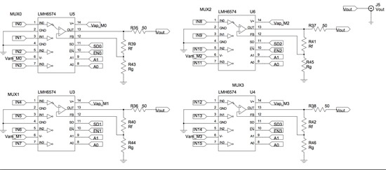
The mux gain is set to ~unity (as suggested in Fig. 29 of LMH6574 datasheet, I use: Rf = 1.5k and Rg is omitted, not accounting for loading by inactive muxes for now).  The mux outputs are series-terminated in 50 ohms, and then read by a coax connected to the scope with 50-ohm termination (see Schematic below).  So there is a 2:1 attenuation between mux input and scope measurement (measured Vout values are 0.05, 0.1, 0.15, 0.2V when mux1 is active, and 0.25, 0.3, 0.35, 0.4V when mux2 is active).

The problem
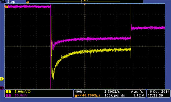
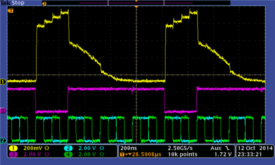
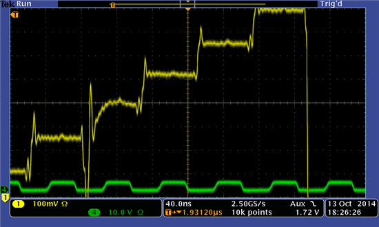
With two muxes powered, Vout shows a long (~500ns) exponential ramp following the transition from the first chip to the second (see Figure 1 below).  No such ramp is seen on address changes within a chip, or at the selection of the first chip.

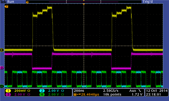
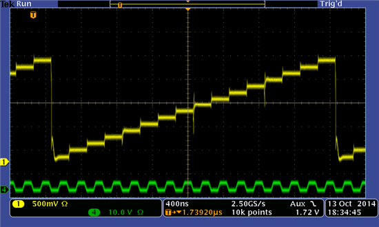
I have probed various places on the board, and do not see this waveform structure on the analog or digital grounds, or on the addressing lines (A0, A1), or on the SD line, or at the mux inputs.  But I do see it on the output of the inactive mux (in this case Mux1) -- See Figure 2 below. 

It appears that the inactive mux is driving Vout.  I don't understand why that would be.  Any help greatly appreciated.

Many thanks,
James

ps: I know from the data sheet that SD (not ~EN) should be used for mux expansion to prevent soft breakdown (when voltage between mux input and output exceed 2V).  So I don't think soft-breakdown is to blame here since (1) as recommended I'm using SD (not ~EN), and (2) there is << 2 V between Vout and unused mux input (and we only see this exponential ramp immediately after the SD transition.

Figure 1
Yellow = Vout of mux pair, after the 50-ohm series termination of both mux chips.  Notice exponential settling at the 5th step (the first step of Mux2).  The Vout signal is transported from pcb to scope via 50-ohm BNC cable.  Scope is terminated in 50 Ohms.

Figure 2
Yellow = Vout of mux (after 50 ohm series termination) seen via coax to scope terminated in 50 ohms.
Pink = output of the disabled mux (mux1, pin 13), probed between the mux and 50ohm series termination.

Mux Schematic:

  • Hi James,

    Have you tried adding delay to the shut-down pin for mux0 & mux1? On page 13 of the datasheet, there is a mux expansion circuit that talks about adding a delay line to the shut-down pin. 

    I am thinking about adding delay line because it seems that there is a fight between the outputs of mux0 & mux1 due to the different inputs presented, when mux0 is disabled while mux1 is enabled. This is not evident on other steps for mux1. 

    Best Regards,

    Rohit

  • Hello James and Rohit,

    In addition to what Rohit has already suggested (possibility that you may need to add a delay), here are my thoughts.

    To Rohit's point:

    I guess one way to tell if the two MUX's are fighting each other or not would be to monitor the supply current into each MUX power supply lead (using a sense resistor or current probe if available) to make sure during the 5th transition waveform, the supply current for MUX1 diminishes in nano-second and does not extend into micro-second time.


    I don't really have an answer but I like to suggest something that you could maybe try:

    The 5th step transition is a larger step (0V to 0.5V) whereas all the other steps are 0.1V each. Is it possible for you to devise an experiment where the MUX2 input voltages are identical to that of MUX1 (0.1V, 0.2V, 0.3V, and 0.4V) so that the 5th step transition is also 0.1V. If the problem goes away, then we can tell that the size of the voltage step is a culprit in the slow settling.

    Regards,

    Hooman

  • Dear Rohit and Hooman,

    Thank you for the suggestions.  Another colleague had also suggested that if two muxes are in competition, even for a short time, then the load on the new mux can heat up the new mux and the thermal time-constant may be the cause of the ~microsecond settling seen immediately after the transition (on step #5).  I do like your suggestion to add a delay, and will try it out (though it will take me some time to configure for that test).

    I will also test the effect of the amplitude of the transition on the settling time.  I can rather easily swap the input voltages to the two muxes and see if the settling follows the input voltages or stays with the mux. 

    Many thanks for the quick replies! 

  • OK, some more information:

    1) The problem is not due to a large voltage step at Mux2.  I changed the ordering (so Mux1 got 0.5, 0.6, 0.7, 0.8V and Mux2 got 0.1, 0.2, 0.3, 0.4V).  There is still an exponential ramp at the Mux1-->Mux2 transition.

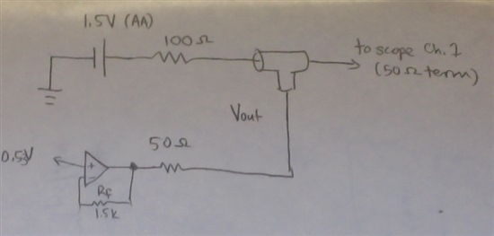
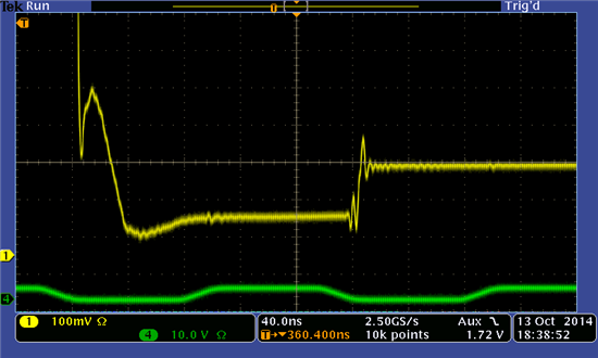
    2) I did a second test that shows the problem is not a timing issue between muxes.  To do this, I remove Mux2..4 from the system (by depowering them and also by removing their output series resistor so that only Mux1 drives Vout).  I then apply 0.5V to all inputs, and a DC bias of 0.5V to Vout (circuit below).  In this configuration, departures from 0.5V at Vout indicate currents sourced/sunk by Mux1.  Ideally, when in Shutdown, Mux1's output impedance should be high and there should be no departure.  But in fact I see that Vout sags when Mux1 is *dis*abled.  I interpret this as a low output impedance at Mux1, even hundreds of ns after Mux1 receives the SD signal.

    So my questions are:

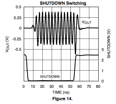
    * How do I interpret this behaviour in the context of Fig. 14 of the datasheet that shows Vout ramping down within ~10ns of SD assertion (plot shown below)?  I guess that the problem I see does not show in that diagram because in that case the signal returns to ground, while in my case "baseline" is 0.5V.

    * Are there alternatives to the LMH6574 that don't have this behaviour?  For example, I know about the OPA4872 which is pin-for-pin compatible, but don't know if it shares this problem. Or if there are other chips that could be viable alternatives.

    Many thanks for your help,
    James

    Test Circuit
    (mux is at bottom left, with 0.53V at input, and with 1.5k feedback resistance and 50ohm output termination.

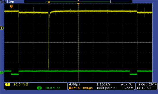
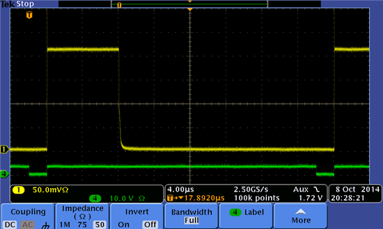
    Yellow = Vout as measured by 50ohm terminated scope via coax.  Notice the huge dip when Mux1 receives the SD signal.  This dip lasts ~300ns (see next image).  A 0.5V offset is applied to Ch1 of the scope.
    Green = logic counter pulse indicating end of a cycle.  Mux1 is active for the 8us following the return of this signal to ground

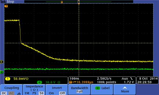
    Zoom of the above showing the ~100mV dip and ~300ns ramp back to baseline.

    Figure 14 from LMH67574 datasheet showing ~10ns lag between assertion of SD and return to baseline.

  • Hi James,

    Your testing seems to point towards shutdown state tri-state impedance in shutdown affecting results. Here are some suggestions:

    1. I know that using the enable pin is discouraged in the datasheet, for the purpose. I am tempted to try Enable pin instead of shutdown just for testing.

    2. What if you changed your MUX connection so that the MUX outputs are directly shorted to each other (so that any shunt impedance in shutdown has less effect), as shown here (note the single 75ohm output resistor feeding your load).


    Done this way, it seems like the active MUX will be in a better position to enforce the output voltage even with the shutdown MUX presenting a finite shunt impedance.

    3. Have you experimented with the lowering RF value from currently 1.5kohm?

    4. Is your layout fairly tight and low capacitance similar to the LMH6574 EVM?

    http://www.ti.com/tool/lmh730276

    5. Have you proved the shutdown pin voltage makes clean transitions with a sharp edge right at the device pin? I'm trying to eliminate the possibility that the logic edge is clean and sharp at the device pin.

    Regards,

    Hooman

  • Hooman,

    Thanks for the suggestions.  Here's what I know so far:

    1) Use ~EN instead of SD
    I had already tried the ~EN (instead of SD).  With ~EN, I do not see ~0.5us transients on chip de-select when Vout is held at 0.5V (as in the test above).  But I do see ~200ns ramp-down if Vout is grounded through a 100 ohm resistor (take the hand-drawn circuit above and replace the 1.5V battery with a ground connection).  Please see image below.
    So it seems you can't win... Long-duration settling time seen with both ~EN and with SD (but one settles slowly to a DC level while the other settles slowly to ground). Is there a clue in this result?

    2) Tie mux outputs together directly, have single series termination resistor.
    I haven't tried this test yet, but I will

    3) Lowering Rf from 1.5k
    Haven't tried this yet, but I was planning to test a gain of 2 anyway (Rf=Rg=575 Ohms).  Are you suggesting a test with Rg still omitted, but with Rf smaller?  I can certainly try both.

    4) Tight layout of mux?
    Yes, I followed the eval board layout very closely.  But please let me know if you see something problematic (image of layout below).

    5) Clean transition of SD at mux pin?
    Yes, I see a clean SD signal at the mux pin (see image below).

    Thanks again for your help,
    James

    Question #1:  Using ~EN instead of SD.  Only one mux present.  All mux inputs held at DC potential (0.53V).  Yellow curve = Vout probed by scope (coax with 50 ohm termination).  Vout also connected to ground via a 100 ohm resistor.  See a long-duration ramp to ground (next image zooms in on this ramp).

    zoom of image above.  Shows ~200ns ramp to ground.

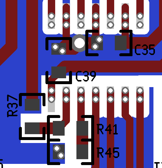
    Question #4: Tight layout?
    Image showing layout in vicinity of one of the 4 muxes, as seen from top side of board.  Mux chip is on the back side, connections with vias in the pads.  Inputs coming in from above, logic signals coming in from below.  Blue is ground plane on back side.  The ground plane does run under the mux chip, but the ground plane has been cleared away from the vicinity of the mux pads.  C35, C39 are 0.01uF ceramics (not shown are 6.8uF tantalums, one set per mux).  R41 is Rf, R45 is Rg and R37 is Ro (output series termination). 

    Question #5: Clean SD signal at mux chip?
    Yellow = Vout in test with 1.5V battery connected to Vout via 100 ohm resistor.  Shows the long return to baseline following the assertion of SD.
    Green = SD line for the mux.  Nice clean edge, no ringing or slow transition.

  • Hi James,

    Regarding the enable pin showing a 200ns ramp-down at disable:

    To me, it seems the slow ramp is something that you observe if you use only the one MUX you are currently working with. With two MUX outputs shorted together, if MUX1 goes into disable slowly, while MUX2 ramps up quickly at the same time, it seems like MUX2 will "force" Vout to follow with whatever input voltage selected on MUX2. Have you tried the 2 MUX arrangement and using enable instead of shutdown and you still have the slow ramp issue at the transition time?

    I don't have any experience with OPA4872 that you had mentioned and which looks pin compatible and drop-in replacement with LMH6574. I'm also interested to hear if other people on the forum have any experience with OPA4872 as a MUX in "expansion" mode (more than 4:1).

    Regards,

    Hooman

  • Hooman,

    I began the two mux test you suggested (~EN, with mux outputs shorted together), but saw strange results.  I then backed up a bit to a single mux test.  This time, I removed all muxes from the board except one (I worried that, even if disabled, a mux's presence could affect the output).  So here's the scheme:

    * Mux slots 1, 2, 3 are empty.  Mux4 has an LMH6574.
    * Rf=1.5k, Rg=omitted, Ro=50ohm
    * Output probed by 50ohm coax, to scope terminated in 50ohms.
    * Vin = 1.6V, divided into 16 levels by resistive divider (16x 10ohm resistors).

    As you can see below, when Mux4 is deselected (and when Mux1 would be on if Mux1 were not absent), Vout is not at 0V (as would be expected if Mux4 enters a high-impedance state).  It seems that the problem may be demonstrated even with a single mux -- i.e. the problem may not be due to our implementation of mux expansion.

    Here are the plots:

    Yellow=Vout, Pink=~EN, blue+green=addressing lines

    If, however, I use SD (rather than ~EN) to select the chip, then Vout looks good.

  • Hi James,

    One other thing which you can try is configuring the LMH6574 with gain of 2 by making Rf = Rg = 575ohms and see if the MUX2 output comes up quicker than the case with only Rf = 1.52kohms & Rg omitted.

    I am wondering if the Rf in unity gain is too high to make the feedback overly damped which could be a reason for the glitch in Vout due to SD to rise up slowly. I think this could also be demonstrated if Rf in MUX2 is reduced from 1.52kohms to 1kohms on MUX2 as Hooman was suggesting. If the supply currents start changing abruptly with the use of Rf = 1kohms, then I would suggest to bump it up to 1.2kohms.

    Best Regards,

    Rohit 

  • Hi James,

    I saw your waveforms with a single LMH6574 using either ~EN and SD. I was hoping that you have some data with at least two LMH6574 outputs shorted together and by using ~EN to select. You said that you saw "strange results" with more than one LMH6574 output shorted together. I wonder what that might have been? Oscillations?

    I've requested some samples and EVAL board to do some testing of my own to see if I can also observe your findings and to see if I can recommend any solutions.

    I will keep you posted on this forum.

    Regards,

    Hooman

  • Hooman,

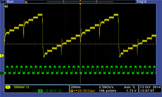
    Thanks for the reply.  Apologies for being vague on the mux-outputs-shorted test.  There were many different "features" of that test and I wanted to see if I could understand them a bit more before posting (hence the 1-mux test).  But here are plots of 4 LMH muxes with outputs shorted together and using ~EN to select.

    The first plot (PLOT A) has a full-scale input voltage of 1.6V.  You can see that the output is a mess.  The 4th mux levels are merged together.  By reducing Vin to 1.0V, I begin to resolve the levels in Mux4 (PLOT B).  But notice that in both cases, the Mux4 --> Mux1 transition does not settle in time for the first level of Mux1.  Even at 1.0V, the mux3->4 transition is not good enough either (PLOT C).  With the clock slowed down to 5 MHz, all levels settle properly (PLOT D), even the mux4-->1 transition (PLOT E).

    Thank you very much for your effort to investigate this.  I really appreciate your help,
    James

    PLOT A:  Yellow=Vout, Green=16MHz clock

    PLOT B: Colors, same as above.
    This time, Vin=1.0V full scale (divided into 16 levels). Mux4 levels look better, but the Mux4->1 transition is too slow.  Also, the other mux transitions don't quite settle in time either (e.g. see a zoom in on the 3->4 transition below).

    PLOT C:  colors same as above
    Zoom on the Mux3->4 transition (the rounded edge, -100ns from middle of screen).

    PLOT D: Slowing the clock down to 5MHz

    PLOT E: 5MHz clock, zooming in on the Mux4-->1 transition.  Vout settles after ~90 ns.

  • Oh, I should have added:  in the test above, I have a gain of 2, with Rf=Rg=590Ohms.

  • Rohit,

    Thanks for the suggestions.  As you'll see in my recent post, I tried with Rf=Rg=590ohms and outputs of muxes shorted together.  That helped, but did not solve the problem. 

    This may be a really basic question, but re: monitoring the supply currents, are you suggesting that I monitor the currents at the mux pins?  If so, do you have a recommendation on how to do that (given that I don't have a current-sense resistor present on the board)?  I suppose I could lift a MUX pin, but that seems overly intrusive.

    James

  • Hooman Hashemi said:

    I saw your waveforms with a single LMH6574 using either ~EN and SD.

    Is it not a red-flag that Vout does not return to ground after the de-selection of the mux in the single-mux test (using ~EN)?  I expected that the output would return to ground, but maybe I'm missing something basic?

    Thanks,
    James

  • Hi James,

    Some comments:

    1. Artifacts of using ~EN: I wonder if your Plot A from your post today (10/13/14) is because of what the LMH6574 datasheet states:

    "Also, care should be taken to ensure that, while in the disabled state, the voltage differential between the active input buffer (the one selected by pins A0 and A1) and the output pin stays less than 2V."
     
     
    Since your terminated output voltage is around 2V peak, it seems like the LMH6574 output pin is about 4V (=2 x 2V) and then the 2V differential mentioned above could be the culprit.
     
    2. MUX outputs shorted together vs. through 50ohm isolation: It seems like your settling times have "improved" (ignoring the Plot A nastiness with a large output swing) when you short all 4 outputs directly (rather than through a 50ohm isolation originally tested) while using ~EN to switch between LMH6574's. Have you experimented with the directly shorted output(s) while using SD pin (may be you have in your prior posts, but I could not specifically locate this condition)?
     
    3. 16MHz vs. 5MHz clock: I am scratching my head right now to find an explanation as to why switching settling is better with 5MHz (Plot D) vs. 16MHz (Plot B) clock, although one is at 400ns/div and the other is at 200ns/div! Is Plot D settling acceptable in your application (not considering that you have dropped your clock rate to 5MHz, but only considering the switching characteristics for now)?
     
    I will be getting my samples + EVAL board by tomorrow and I hope to have something working on the bench by Wednesday.
     
     
    Regards,
    Hooman

  • Hooman,

    1) Yes, I think you are correct that this could be the "soft breakdown" mentioned in the datasheet.  One solution would be to implement the ~EN-then-SD logic.

    2) Yes, with outputs shorted together, the settling improves.  I have tested 4 muxes with outputs shorted and SD (see plot below).  The Mux4-->1 transition is better with SD than with ~EN, but the 2->3 and 3->4 transitions are worse (and don't settle in time).  See PLOT F below.

    3) By my read, the settling time is no different between the 5MHz and 16MHz clock experiments (e.g. for the 4->1 transition it takes ~80 ns).  It's just that at the lower clock rate, the mux spends more time at each level, so that 80 ns is a smaller fraction of the total step duration, and so the voltage can happily settle before the next address (or chip) transition.  In fact, at 16MHz, the step duration is 62ns and so after the 4->1 transition, Vout doesn't have time to settle before mux1 switches to its second input.  So to answer your question, no, the switching characteristics seen in Plot D are not adequate for my application because I need to settle well before 62ns after the mux-to-mux transition.

    James

    PLOT F
    Yellow=Vout with 4 LMH6574 chips, outputs shorted together, Rf=Rg=590ohm.
    Green=16MHz clock

  • Hi James,

    I have done some work with LMH6574 MUX expansion (using 2 MUX's) and I have some data / comments to share:

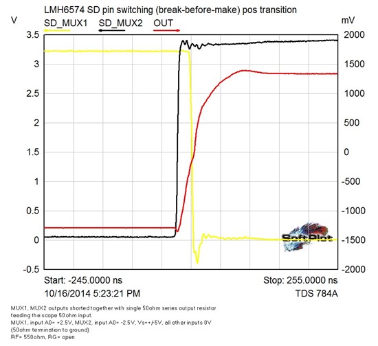
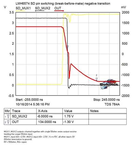
    1. Choose Break-before-Make: With 2 MUX outputs shorted together, the output seems to settle in worst case 130ns as long as I make sure I break-before-make (that is, I invoke shutdown in MUX1 before I let the other MUX2 come out of shutdown). The waveforms look uglier if there is any time where both MUX are forcing the output together.

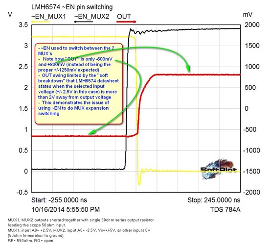
    2. ~EN pin Switching Issues: I have seen ~EN "soft limiting" if I try to do the MUX expansion using the ~EN pin instead of SD. So, I think ~EN in this application is not to be considered (unless you keep your MUX input voltages at 1V or below)

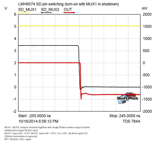
    3. MUX Shutdown Transient as Culprit: Each MUX by itself responds to SD pin in about 20ns (both going into shutdown and coming out). This does not change if a 2nd MUX output is shorted to the 1st MUX output and the 2nd MUX is kept in SD all the time (no swtiching). So, it's only the transient behavior of the de-selected MUX which is slowing down the response. It is conceivable that in your situation, where you are de-selecting 3 MUX's, the delay could be worse than the 130ns I've measured with de-selecting only one.

    Here are some of my waveforms for your review:

    Positive Output Transition:

    Negative Output Transition:

    Individual MUX going into Shutodown and coming out of Shutdown:

    Going into Shutdown:

    Coming out of Shutdown:

    I don't think I really have a solution for your application. I wanted to make sure I also see the slow settling with more than one MUX output shorted together, even if I'm only using 2 total MUX's and you have 4. More importantly, I wanted to make sure that each individual LMH6574 switching is fast (less than 20ns) which I've confirmed to be true.

    Let me know if you have any thoughts.

    Regards,

    Hooman

  • Dear Hooman,

    Thank you for taking the time to run these tests.

    If I understand correctly, you have found similar results to what I have found -- that the settling time with mux expansion is larger than 100 ns.  The LMH6574 datasheet (Figure 14) suggests SD switching completes in ~20 ns, and there's nothing elsewhere in the datasheet to suggest that mux expansion degrades this performance -- in fact, the datasheet recommends mux expansion as an application of this chip.  Either we're both implementing mux expansion in a non-optimal way, or there is a timing limitation with mux expansion that is not present in a single-mux setup.  If the latter, then hopefully the datasheet would be updated accordingly.

    Also, a point of clarification: in #2 above you say:   "I have seen ~EN "soft limiting"" which I  take to be a synonym for what the data-sheet calls "soft breakdown."  Is that correct?  What are the symptoms that you see (could you post a plot)?

    Again, thank you for all of your help on this!
    James

  • Hi James,

    Yes I meant "soft breakdown" instead of "soft limiting" per datasheet wording.

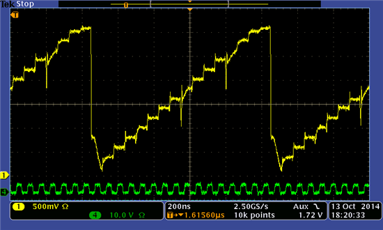
    Here is what I get when I use ~EN for switching (The OUT voltage is lower than expected / what it should be - evidence of some sort of clamping). Note that I am using a +/-2.5V DC input voltage and OUT should have been 1.25V because of the 6dB attenuation due to 50ohm series output resistance looking into 50ohm:

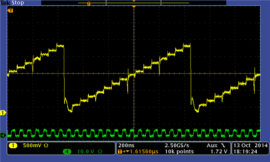
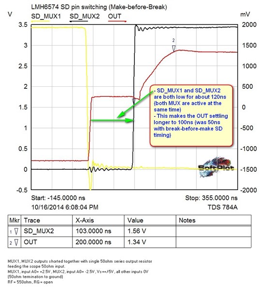
    By the way, for reference, here is what happens if you make-before-break the 2 MUX switching where the settling gets much worse:

    Thanks for bringing attention to this issue.

    We may in fact edit the LMH6574 datasheet and add information about the "MUX expansion" application and how switching off one LMH6574 may slow the response to about 140ns.

    I will discuss this with the rest of the team and post a response here shortly as to how we plan to proceed.

    Regards,

    Hooman

  • Hi James,

    FYI: The LMH6574 (as well as the LMH6570) datasheets have been updated to show the expected response time when using MUX expansion using the Shutdown (SD) pin.

    Regards,

    Hooman