This thread has been locked.

If you have a related question, please click the "Ask a related question" button in the top right corner. The newly created question will be automatically linked to this question.

OPA847 transimpedance application

Other Parts Discussed in Thread: OPA847, TINA-TI

removed.

  • Hello Dom,

    To answer your question:

    1. Question: "Below: Loop gain amplitude + phase. both Cf result in less than 45degrees of phase margin at some point before 0dB. Is there a way to correct this, could that be causing the ringing?"

    Answer: The low open loop simulated phase margin, at loop gain values above 0dB, should not be a concern. It is the phase margin at 0dB loop gain which is the ultimate determinator of stability (or instability).

    Here are some comments of mine:

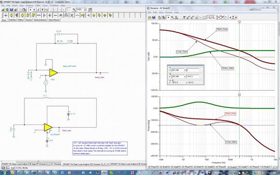
    With OPA847 requiring a minimum noise gain of 12V/V (21.6dB) for stability, with the conditions you've specified, I see that beyond a value of CF = 1pF, you could run into instability as the intercept point (NG with open loop gain) is at or below y-axis value of 21.6dB. Simulation below is with CF= 1pF and the simulated phase margin (39 deg.) is lower than one would hope already!

    TINA-TI file for the simulation above:

    2664.OPA847 TIA Open Loop Analysis E2E Hooman 10_27_14.TSC

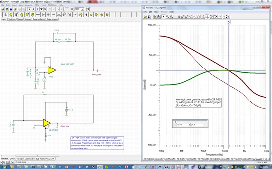
    Noise Gain Increase: For a more manageable / practical range of CF values that achieve stability, I would recommend a method to raise your high frequency Noise Gain, such as adding a series RC shunted to ground. Here is the intercept point improved from 19.5B (no shunt RC) to 24.1dB(with shunt RC):

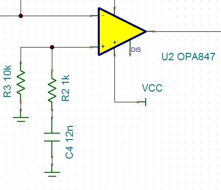
    Non-inverting input: I've also had TIA cases where I've had improved stability if the non-inverting input (AC grounded in your circuit) is changed as shown such that this OPA847 node sees a finite impedance (~910ohm) to ground at higher frequency. The stability effect of such a change may (or may not) show on the bench but it is something that is not modelled in TINA-TI:

    Regards,

    Hooman