This thread has been locked.

If you have a related question, please click the "Ask a related question" button in the top right corner. The newly created question will be automatically linked to this question.

LMH6518 output clamping question

Other Parts Discussed in Thread: LMH6518, ADC08D500

Hello!

I'm considering LMH6518 for an application where its output will be often overdriven a lot. Something like an 1000-2000% overdrive if I understand the term correctly. I mean, the "virtual" unclamped output swing will be 10 to 20 times higher than clamp voltage and hence the real resulting output swing.

This will happen only with high gain settings and input swing will be still in an acceptable range for the amplifier.

But overdrive recovery is an important parameter for this design. And clamp overshoot may be a problem. Or may be not.

The LMH6518 datasheet specifies overdrive recovery time only for 50% overdrive.

Is there any extended information available for LMH6518 overdrive recovery time and may be for clamping overshoot?

  • Hi Anatoly,

    Sorry for the delay in reply. I will have to check whether there is any data realted to overdrive recovery time or clamping overshoot available for LMH6518 beyond the 50% overdrive mentioned in the datasheet.

    Usually in the case where the input swing is in an acceptable range for the amplifier with the gain set to its highest, the output amplifier of LMH6518 would already be saturated or beyond the 1dB compression point. And the output clamp is basically limiting this distorted output voltage into the ADC. In that case, it would be best to have an automatic gain control loop so that the output is in acceptable range without distortion for the receive path and clamp overshoot may not be that severe as compared to overdrive recovery time .

    What application are you planning to use the LMH6518 for? Also, do you know what is the average acceptable input signal level (A) that you are targetting which would amount to Ax10 or Ax20 higher clamp voltage level? Also, what is the input signal bandwidth that you are looking at?

    Best Regards,

    Rohit

  • Thank you for your reply!

    The application is signal registration for some scientific setup. Input signal is expected to be at about zero in average with positive peaks (spikes). Signal bandwidth is from DC to about 300 MHz.

    The goal is to skip some "high" peaks and to digitize lower ones (preliminary with ADC08D500). For example, with gain set to 30 dB (HG, ~9 dB atten.), "low" peaks up to 22 mV high at LMH6518 input will be amplified to "correct" 0.7 V level relatively undistorted (>50 dBc SFDR up to at least 250 MHz according to figures 25, 26 of the datasheet). But "high" peaks in this case can be up to 350 mV high at LMH6518 input and will lead to output clamping and awfull distortion, which is OK as far as we skip these peaks and some measurements after them to allow the amplifier to recover. As a result, the amplifier recovery time determines how close in time the "low" peaks could be to "high" ones.

  • Hi Anatoly,

    Sorry, I don't have any data for greater than 50% overdrive condition. I have ordered an evaluation board and hope to get that data to you soon.

    Best Regards,

    Rohit 

  • Thanks, I appreciate your effort very much!

  • Hello Rohit!

    Is there any progress with that data?

    We are about to put the amplifiers in to our design, but if the recovery will be to long, we'll have to respin the board and try something else...

    Would appreciate the data very much!

    Best Regards,

    Anatoly.

  • Hi Anatoly,

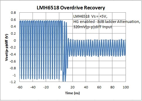
    I have attached an oscilloscope plot of the LMH6518 overdrive recovery when it is driven with 350mV(p-p)diff and its settling to the lower input signal level. The ac outputs recover faster from clipping compared to the output common mode operating point which sets the overdrive recovery longer for approximately 1000-2000% overdrive condition at about 3usec. It is probably because the output buffers are saturating at such a high drive level.

    Test conditions were with 300MHz input signal level, and the gain of LMH6518 set to 30.8dB (HG enabled with ladder attenuation set to 8dB) and the device is set in full power mode.

    Best Regards,

    Rohit

  • Thanks a lot! The information is very useful.

    Could you please also post a closer view to the transition region to see the AC recovery time?

    Could you also please clarify the measurement setup - is the measurement done with single-ended or some kind of differential probe? If the probe was single-ended, can the common mode problems be the consequence of asymmetric loading of the output buffer?

  • Hi Anatoly,

    The AC recovery time for the transition region is pretty fast, close to 15ns.

    The measurement was done by dc coupling both the outputs going directly into the oscilloscope inputs. Sometimes the common mode problems could be a consequence of asymmetric loading of the output buffer. But, in this scenario it seems because the drive is at such a high level with High Gain mode enabled, the output amplifier internal to the part will be saturated. As the outputs are being limited due to the output clamp, the common mode loop breaks and it is this common mode loop break recovery was what we were seeing. That being said the output amplifier recovers fairly quicker from saturation. I think this is normal behavior for any fully differential amplifier circuit with 1000-2000% of overdrive levels. 

    Best Regards,

    Rohit

  • Thank you very much for the replys!