This thread has been locked.

If you have a related question, please click the "Ask a related question" button in the top right corner. The newly created question will be automatically linked to this question.

THS7353, ADC10080 - Example schematic for Video Application

Guru 19775 points
Other Parts Discussed in Thread: ADC10080, THS7353, THS7303

Hi Team,

Please advise me proposing a solution for a HD Video A/D conversion.

In order to fully utilize the ADC10080 dynamic range, it is necessary to make coincide pedestal level (Back porch level) of the HD analog  video Y input to VrefB of ADC10080, and  Pb, Pr to VCom of ADC10080 respectively.

Can you provide us an example schematic which implement this request?


I think THS7353 has on-chip DC-Restore circuit. I am wondering if this can be used to implement this function.


 Best Regards,
Kawai

  • I had forgot to insert the figure.

    Best Regard,
    Kawai

  • Hello Takushi-san,

    Although the THS7353 has dc restortion circuit, I would recommend using the THS7303 as it has the SAG correction in-built in addition to dc restortion circuit (AC sync tip clamp) which is convenient for separating the output common mode of THS7303 with the input common mode of ADC10O80.

    Also, in-order to fully utilize the dynamic range of ADC10O80, the input common mode voltage of the ADC10O80 must be maintained close to Vocm and it is specifically mentioned in the datasheet to not load the Vrefb pin.

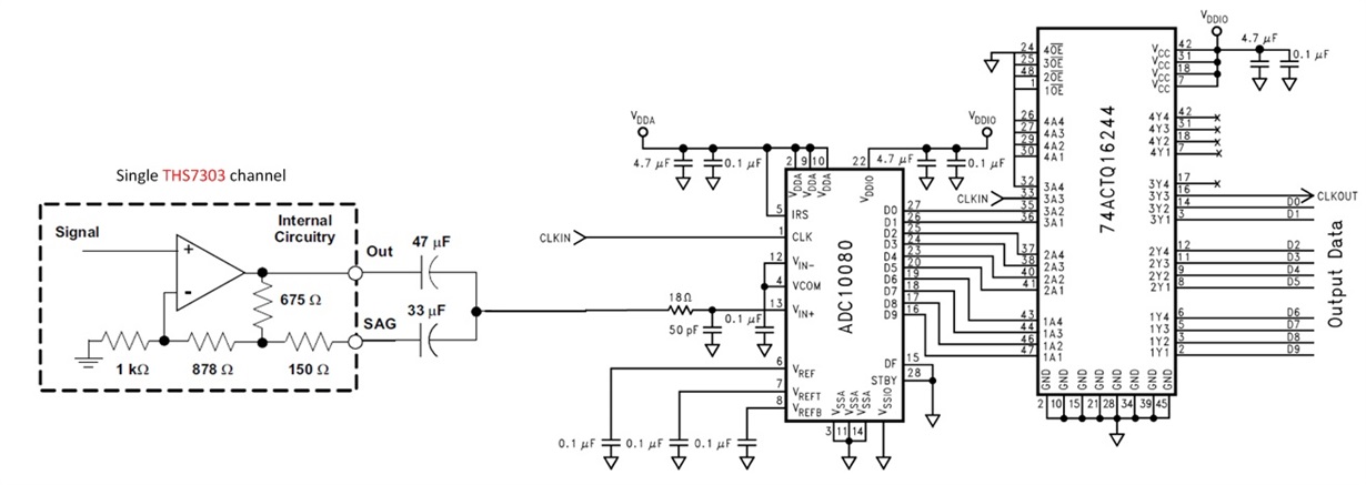
    Below I have attached a rough schematic of interfacing the THS7303 (single channel) with ADC10O80 which is in single-ended input configuration using the Vocm pin. I have not shown the THS7303 input structure but, please refer to the page 27 "Input Modes of Operation: AC sync tip-clamp" for operating the THS7303 input in dc-restortation circuit.

    Best Regards,

    Rohit

  • Hello Rohit-san,

    Thanks for the advice.

    I believe pedestal level (Back Porch / Black Level) would not coincide with the ADC10080 000h level depending on APL (Average Picture Level) using this schematic, wouldn't it ? It seems that you would need to somehow sample and hold the pedestal level and adjust the offset voltage before ADC10080 input.

    Do you have any idea ?

    Best Regards,
    Kawai

  • Hello Takushi-san,

    The pedestal level (back porch/ black level) should coincide with the ADC10080 000h level using this schematic because the pedestal level (back porch/black level) will be level shifted to the common mode input voltage of the ADC. Below the 0V DC which represents the pedestal level of the video signal will be level shifted to the ADC input common mode voltage  with the peak white level and sync levels being shifted with respect to the ADC common mode voltage as well.

    For any ADC, the voltage swing close to the common mode input voltage represents a code closer to 000h which would be the case with the above schematic.

    .

    Best Regards,

    Rohit

  • Hello Takushi-san,

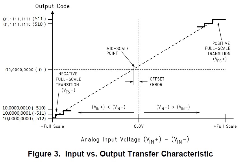
    I take back my word that the voltage at the Vcm corresponds to code of 000h from the above "Input vs Output Transfer Characteristic". If you literally look at the offset binary output data (which is what the above curve is), the Vcm would correspond to an integer value of 512 which is the offset binary format data which is what you were referring to. 

    But, if you look at the 2's complement data, the Vcm would correspond to 000h data or 0 integer value. ADC10080 supports both the offset binary and 2's complement data format. As such, the above proposed schematic should work for your application.

    Best Regards,

    Rohit

  • Hello Rohit-san,

    Thank you for your reply and I am sorry for my delay.

    It seems that ADC10080 could only output in offset binary and 2's complement data format. In this video application case, it seems that the ADC would be only used from 000h to 1FFh (9-bit), so only half the dynamic range of the ADC would be used, am I correct ?

    If straight binary data format type ADC is used instead of ADC10080, do you have any idea how to coincide the black level of THS7303 output to ADC 000h, bottom of dynamic range ? THS7303 is used as sync tip clamp and output would be AC coupled, so the average level (APL) would differ by the picture of each timing.

    Best Regards,
    Kawai

  • Hello Kawai-san,

    In the 2s complement data format, you should be able to utilize full dynamic range of the ADC. I have attached similar input vs output transfer function posted above but in 2s complement form. When the black level of the video signal coincides with the Vcm of the ADC, the output should be 000h in 2s complement data format. The sync information in the video signal can be extracted from the negative going codes corresponding to Vcm - 300mV level.

    The only way I know of coinciding the black level of THS7303 output to ADC 000h code is using 2s complement which I have described above. I would recommend posting questions on the High Speed Data converter forum if further clarifications on the ADC10080 data format is needed.

    The THS7303 output even though is shown as AC coupled in the above schematic, it is used in SAG correction capability; which means that the field or line tilt in the video signal should be minimal (because an additional gain path due to the feedback capacitor compensates for the loss close to dc) and thus should maintain the black level at the input of ADC close to Vcm.

    Best Regards,

    Rohit