This thread has been locked.

If you have a related question, please click the "Ask a related question" button in the top right corner. The newly created question will be automatically linked to this question.

Increased phase delay in some THS3001

Other Parts Discussed in Thread: THS3001

Hey guys

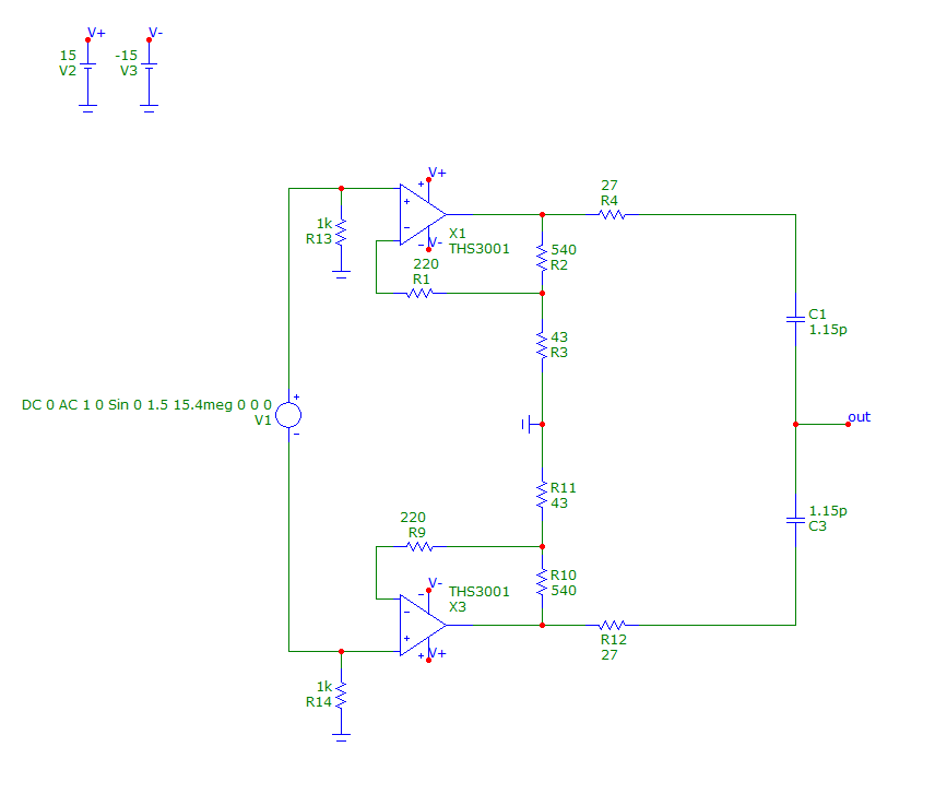
I'm running out of Ideas on how to resolve this problem. I have a high speed diff amplifier composed of two THS3001 according to the attached simplified schematic.

The 15.4MHz-Signal, which is amplified by the two THS3001 to 16Vpp each (32Vpp diff) is fed to a precision capacitive bridge. The remaining signal at the "out"-node therefore has a very small amplitude (~10mV) and is afterwards demodulated by means of an IQ-Demodulator.

Now my problem is that in the first four badges of 15 PCBs each, there have been overall two Boards that showed excessive phase delay in the two THS3001. This additional delay cannot be measured with an oscilloscope, but only with the amplified Q-output of the mixer. I checked every resistor and capacitor value around the amplifier circuit, but it wasn't until I changed the Amps before the phase delay returned back to the normally measured value.

Does anyone have an idea why there are some Amps that show this behavior or what event could cause such an error?

Thanks for your help!

  • Hello Fabian

      The issue I believe is with the R1 & R9 resistors you have inserted into the feedback. The closed loop gain of Current Feedback amplifiers(CFA) are sensitive to the inverting terminal's input impedance. For the THS3001 it is 15Ohm, however with the external resistors you added you are greatly increasing the effect of the inverting input resistance on the closed loop gain. Please see below attached application note on estimating closed loop gain of CFAs

    http://www.ti.com/lit/an/snoa366b/snoa366b.pdf

    I also ran a TINA simulation with R1/R9 of 220Ohms and 0Ohms. The BW changes from 38MHz to 260MHz. As you can see having the 220Ohm resistance is severely limiting your BW to close to your desired signal needs which is causing you potential issues. Was there a reason you added those resistors?

    THS3001.TSC

    -Samir

  • Hi Samir

    The Resistors R1 and R9 were added respectively increased after a lot of PCBs showed oscillations because of the parasitic capacitances that come with the capacitive bridge configuration. I didn't want to change both, Rf and Rg, so I increased the feedback resistors R1 and R9 to lower the bandwidth. But I see your point, so I'm going to do some experiments with the resistor values.

    Is there any other reason for this behaviour, I mean an internal one? Can it be that there are some components in the Chip that are much more sensitive to thermal and electrical stress than others? I did notice that the THS3001 is somewhat more sensitive to hand-soldering than other amps and one has to give much more attention to the right soldering temperature in order to not damage the part.