This thread has been locked.

If you have a related question, please click the "Ask a related question" button in the top right corner. The newly created question will be automatically linked to this question.

LMH6629 transimpedance amplifier; 1. I'm using a low (62 Ohm) feedback resistor; 2. Compenstated and similar plug-in replacement for the WDFN-08 packaged version of this LMH6629?

Other Parts Discussed in Thread: LMH6629, THS4271, TINA-TI, THS4211, THS4051, THS4081

Hi,

I'm using the LMH6629 amplifier in the first stage of a transimpedance amplifier connected to an IR detector that has 200 pF of shunt capacitance and 1 kOhm of shunt resistance.  I use a rather low 62 Ohm feedback resistor with a 39 pF compensating cap across it.  I leave the COMP pin unconnected so that the default compensation is 4V/V stable.  I used LTSPICE to check the stability, and it will show oscillation if the inductance of the cable is greater than about 12 nH.  This is because the noise gain drops below 4V/V when the noise gain curve intersects with the LMH6629's open loop curve, due to the inductance. I started playing with the compensation cap value in SPICE to see if that helps, but haven't finished with the simulation yet.   I have several options I'm exploring but have a couple of questions I'd like to post here:

Question 1  - Is there any problem with using a 62 Ohm feedback resistor?

Question 2 - I use an asymmetric set of supply voltages +4V and -1.2V.  Is there any problem with that?

Question 3 - Is there a compensated, similar op-amp in the same WDFN-08 package that has the same pinout as the LMH6629?


Ken

  • I am attaching a schematic of the transimpedance amplifier

    Transimpedance Amplifier LMH6629 1st Stage.docx

  • Hi Ken,

    To answer your questions:

    Question 1  - Is there any problem with using a 62 Ohm feedback resistor?

    Response: The feedback resistor looks like a load to the output (62ohm in this case). Apart from that, I don't see any issues (LMH6629 output current capability is large, so typically this should not be an issue).

    Question 2 - I use an asymmetric set of supply voltages +4V and -1.2V.  Is there any problem with that?

    Response: I don't see any issues with that as long as the attainable output swing (-0.38V to 3.2V typical assuming RL=100ohm to Vs/2) is what you're looking for.

    Question 3 - Is there a compensated, similar op-amp in the same WDFN-08 package that has the same pinout as the LMH6629?

    Response: The closest approximation to the LMH6629 behavior in a "similar" package (DRB) would be the THS4271 (Part number: THS4271DRBT), but the pinout is not the same (it is unity gain stable though). Sorry!

    THS4271DRB
    Super-Fast Ultra-Low Distortion High Speed Amplifier in 8 Pin VSON

    Temperature Range: -40 to +85 °C

    Package Type: VSON
    Channels: Single
    1K OEM Price: $2.78

    All values are typical unless otherwise noted.

    VccMin: 5 V
    VccMax: 10 V
    VinMin: 1 from V- rail
    VinMax: -1 from V+ rail
    VoutMin: 1 from V- rail
    VoutMax: -1 from V+ rail
    Offset voltage (Max): 10 mV
    TcVos (Typ): 10 uV/°C
    Bias current (25°C Max): 15 uA
    Supply current (Max per Ch): 24 mA (per channel)
    Output current: 80 mA
    Open loop gain: 75 dB
    Slew rate: 1000 V/us
    Bandwidth: 1400 MHz
    Voltage noise: 3 nV/Sqrt(Hz)
    Current noise: 3 pA/Sqrt(Hz)
    Differential gain: 0.007 %
    Differential phase: 0.004 Deg


    Other notes:

    Feedback Type: Voltage
    Rail to Rail Input: No
    Rail to Rail Output: No
    Unity gain stable: Yes
    Described on data sheet(s): THS4271
    Spice model available: Yes
    Package description: 8 Pin VSON: 3.00L x 3.00W x 0.88H mm, 1.00mm pitch
    Drawing: DRB0008A

    Bipolar Input

    Regards,

    Hooman

  • Hi Hooman,

    Thank you so much.

    One question, the thermal pad on the LMH6629 is tied to the negative supply pin of the LMH6629. The data sheet for the THS4271 says to tie the thermal pad to ground. Were I to use the THS4271 in place of the LMH6629, I wouldn't mind so much having to rewire the pins because of the difference in pinouts between the LMH6629 and THS4271, however it would be a problem if I couldn't connect the THS4271's thermal pad to the -VEE plane directly underneath the footprint that was originally made for the LMH6629 on my board. Do you have any idea if I can connect the THS4271's thermal pad to -VEE?
  • Hi Ken,
    You can tie the THS4271 thermal pad to the V- potential, just as you would for the LMH6629. So, in that sense, there is no change.

    Regards,
    Hooman
  • Hi Hooman,

    Thank you for answering my questions.  

    The LMH6629 is oscillating, I have posted a schematic in the thread recently.  If I disconnect the IR detector from the LMH6629 input and simply put a 220 pF resistor in paralllel with a 1 kOhm resistor (to simulate the shunt capacitance and resistance of the IR detector) it still oscillates. My simulation tells shows slight oscillation if there is even 10 nH in series from the resistor and cap to the LMH6629's inverting input.  I suspect that that is either the whole problem or part of the problem.  My questions are:

    How do you recommend I compensate this op-amp because I assume I will never be able to get rid of the series inductance since the LMH6629  is connected to the IR detector by about 2 inches of RG136 cable (67 pF per foot).  I can't reduce the cable length any further.  

         I've noticed in some of your responses to other posters concerning LMH6629 oscillations that you sometimes recommended a ferrite bead connected from ththe non-inverting pin to ground.  I connect a bias voltage to the non-inverting input through a resistor.  This provides bias to the IR detector.  Can you tell me more about the ferrite bead solution?  

        Also, I noticed that you recommend (and the data sheet does too) connecting an RC combination between the inverting and non-inverting pins.  Would this help quell my oscillation?

       I can't increase the feedback resistor which is now 62 Ohms because the LMH6629 has to sink the DC current from the IR detector which can be as high as 50 mA.  My feedback cap is 39 pF.  I am shooting for a -3dB BW of 25 MHz.

    I did not relieve the planes underneath the inverting pin of the LMH6629.  I felt it was not necessary since the feedback cap is relatively high at 39 pF and that the circuit could tolerate the 0.5 pF or so of parasitic capacitance between the inverting pin and any plane underneath it.

    Also,  if the COMP pin floats, is the LMH6629 stable for a gain of 4?

    Regards,

    Ken

  • Hi Ken,

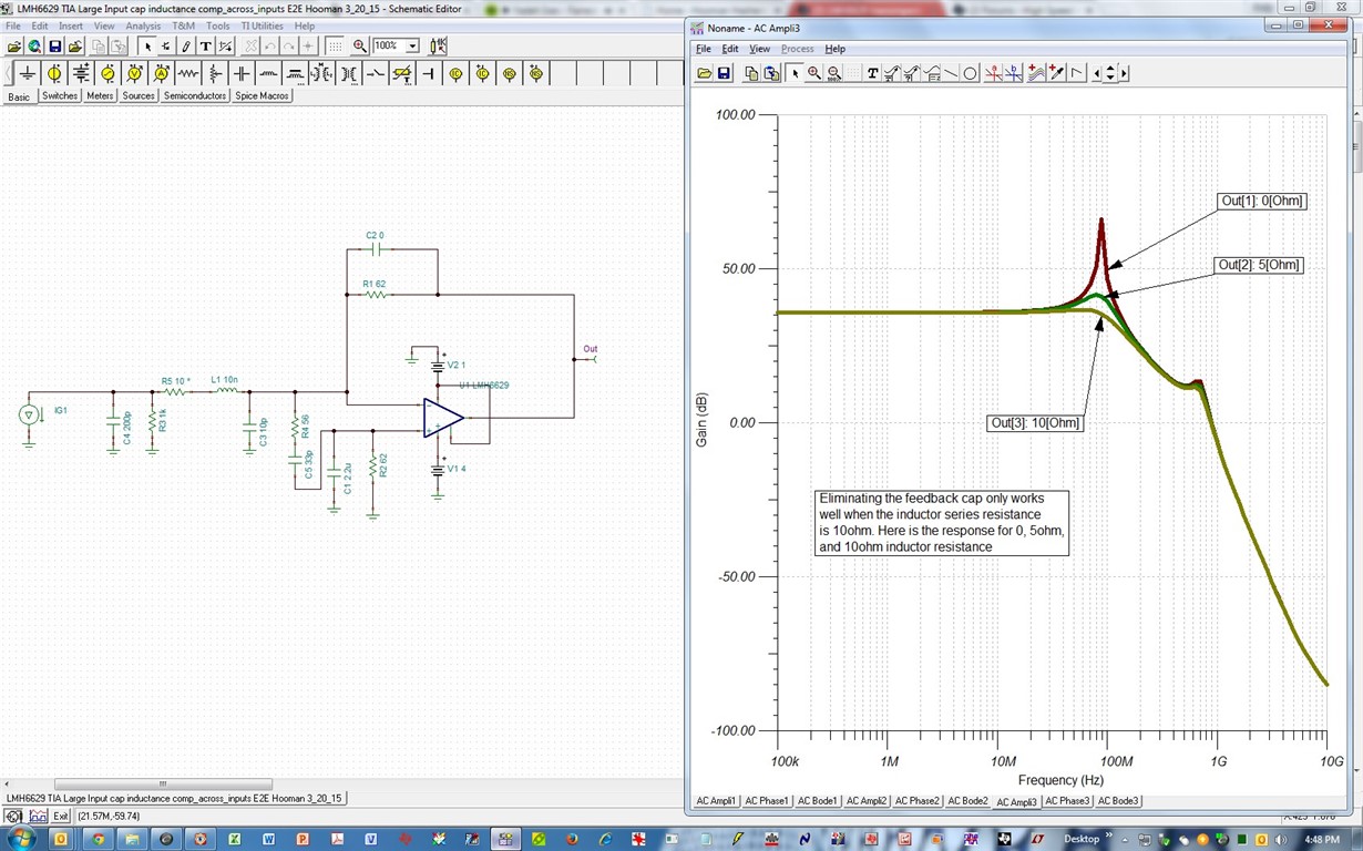
    I can also see in simulation that with your schematic, 10nH of inductance will cause instability. A lower IR capacitance (currently at 200pF) and lower cable capacitance (currently at 10pF) will both help. But I guess you cannot do much about those. Unless you eliminate the coax (67pF/ft) and go with a lower inductance hookup wiring, if you don't need the coax shielding?

    A resistance of 10ohm in series with the inductor helps out a lot in simulation, but I'm not sure if adding this is viable in your application (or if the simulated effect is valid on the bench or not?):

    Here is the TINA-TI simulation file for above:

    /cfs-file/__key/communityserver-discussions-components-files/14/0741.LMH6629-TIA-Large-Input-cap-inductance-E2E-Hooman-3_5F00_20_5F00_15.TSC

    I've also experienced TIA instability with the LMH6629 when the photodiode is at a "distance" (2" to 3") from the inverting node. In the past, I was able to rein in the instability by manipulating the high frequency impedance of the non-inverting input to ground (either adding a resistance or a ferrite bead which increases the high frequency impedance without affecting the noise). Here is a couple of E2E posts that discuss this:

    http://e2e.ti.com/support/amplifiers/high_speed_amplifiers/f/10/p/279825/977388#977388

    http://e2e.ti.com/support/amplifiers/high_speed_amplifiers/f/10/p/300431/1068047#1068047

    I have attributed the calming effect of the non-inverting impedance (at high frequency) to that of a BJT emitter follower where base resistance sometimes quels oscillations (but I'm not 100% sure that the two are analogous).

    Regarding your questions:

    Question:  Also, I noticed that you recommend (and the data sheet does too) connecting an RC combination between the inverting and non-inverting pins. Would this help quell my oscillation?

    Response: I don't think minimum stable gain is your issue (that would be the reason to incorporate the compensation scheme in Figure 50 that you speak of).

    Question: Also,  if the COMP pin floats, is the LMH6629 stable for a gain of 4?

    Response: To set the LMH6629 to 4V/V minimum stable gain, you must tie the COMP pin Low (leaving it open is for min 10V/V gain).

    Hooman 3/20/15: CORRECTION: INTERNAL PULL-DOWN ON THE COMP PIN MEANS THERE IS NO NEED FOR TYING THIS PIN LOW TO GET 4V/V MINIMUM STABLE GAIN OPERATION.

    Question: I did not relieve the planes underneath the inverting pin of the LMH6629.  I felt it was not necessary since the feedback cap is relatively high at 39 pF and that the circuit could tolerate the 0.5 pF or so of parasitic capacitance between the inverting pin and any plane underneath it.

    ResponseI have not experimented with the ground plane left intact under the device. Last resort you could order the LMH6629 WSON package EVM to rule out the impact of the layout.

    Regards,

    Hooman

  • Hi Ken,

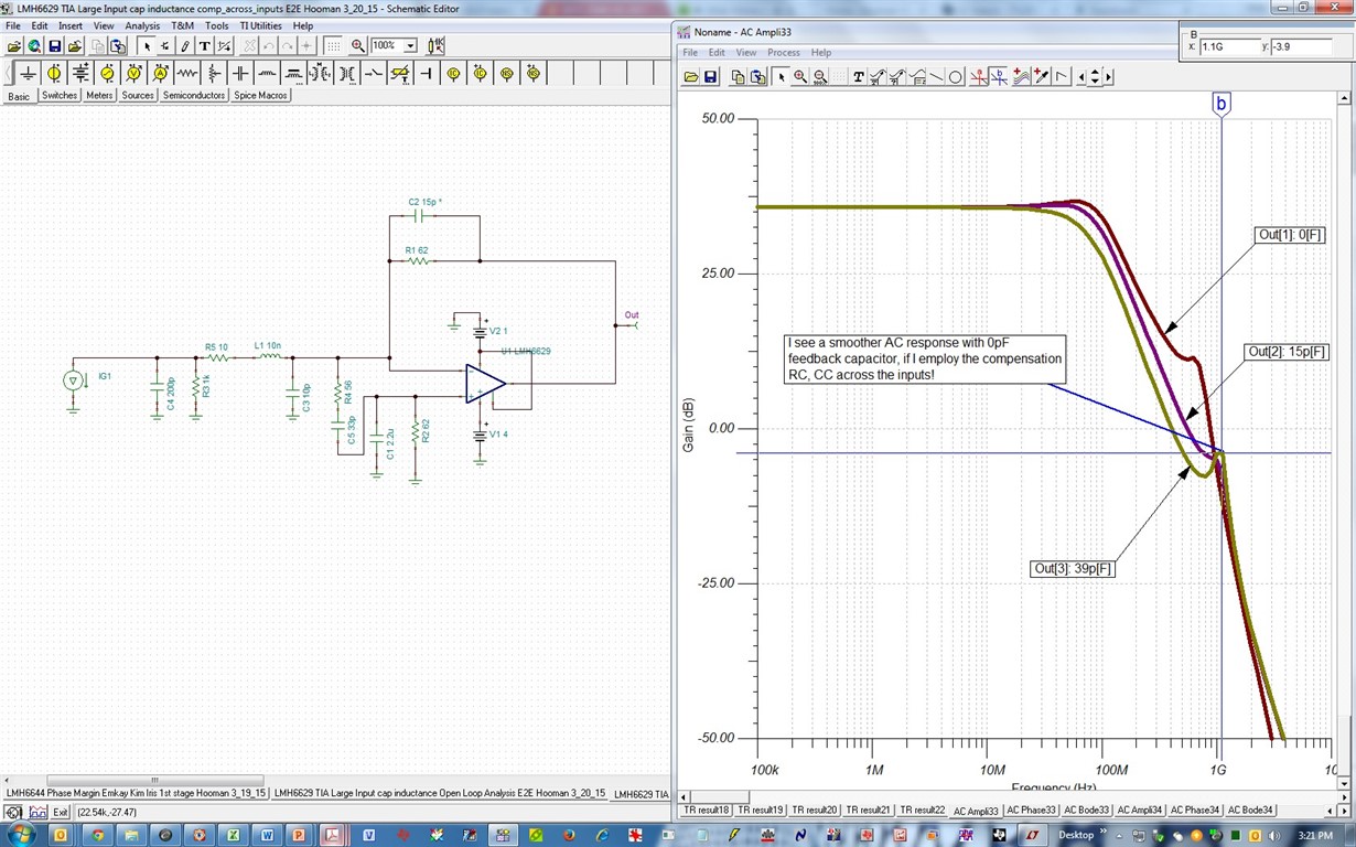
    If I apply the compensation scheme of LMH6629 Figure 50, I can reduce the capacitor across RF (currently at 39pF) to 15pF or 0pF, and get rid of some sharp peaking at 1.1GHz. This is all assuming I can put 10ohm in series with your 10nH inductor. Please take a look:

    TINA-TI File:

    /cfs-file/__key/communityserver-discussions-components-files/14/6232.LMH6629-TIA-Large-Input-cap-inductance-comp_5F00_across_5F00_inputs-E2E-Hooman-3_5F00_20_5F00_15.TSC

    Regards,

    Hooman

  • Hi Hooman,

    Thanks for the response.

    Concerning adding the 10 Ohm resistor in series, that would be a problem since I'm also providing a -50 mV bias to photodiode on that line and at the same time there is up to a 50 mA DC current being sourced by the photodiode, so there would be an unacceptable voltage developed across the resistor. However, what about using a ferrite instead of a 10 Ohm resistor? There the DC voltage drop would be insignificant and I'd get the damping effect at high frequenies. Do you have any thoughts on that?

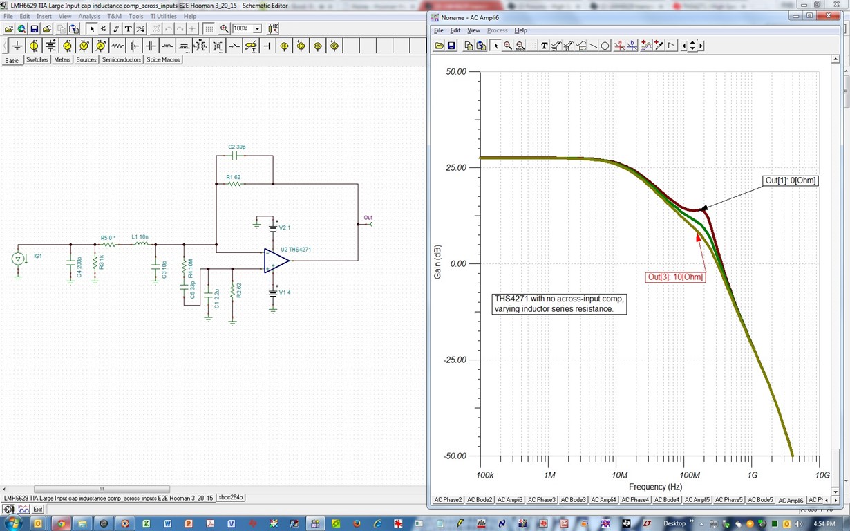
    It looks like I may be out of options. I tried the THS4721 in my simulation model by just replacing the LMH6629 with the THS4721. The -3dB bandwidth of the output of my simulation model dropped when I did that from in the 20's of MHz down to 10 MHz. There was still a little bit of peaking in the frequency response too. Can you plug in the THS4721 into your TINA simulation and tell me if you see this peaking?

    Are you sure about the sense of the COMP pin? The data sheet says that for the WSO8 package, which I am using, the COMP pin is internally pulled down placing it a logic 0 state and the bandwidth is reduced to enable stability at 4V/V. I leave this pin unconnected on my board.


    From LMH6629 data sheet:
    "7.3.2 Compensation
    The LMH6629 has two compensation settings that can be controlled by the COMP pin (WSON-8 package only).
    The default setting is set through an internal pulldown resistor and places the COMP pin at the logic 0 state. In
    this configuration the on-chip compensation is set to the maximum and bandwidth is reduced to enable stability
    at gains as low as 4V/V.
    When this pin is driven to the logic 1 state, the internal compensation is decreased to allow higher bandwidth at
    higher gains. In this state, the minimum stable gain is 10V/V. Due to the reduced compensation, slew rate and
    large signal bandwidth are significantly enhanced for the higher gains."


    Regards,

    Ken

    By the way, I'll have to try the TINA simulator.
  • Hi Hooman,
    I just thought about my idea of putting a ferrite bead in series and that doesn't make sense, since it appears that the small 10 nH inductance is the root of my problem. Adding a ferrite bead would just add more inductance.
  • Hi Hooman,

    That's good, I like that idea. I can' add the 10 Ohm resistor, will I still see any benefit with your proposed compensation scheme if I don't add the 10 Ohm resistor.
    Ken
  • My last post should have read " I can't add the 10 Ohm resistor, ...", not "I can' add the 10 Ohm resistor..."
  • Hi Ken,

    The 0pF feedback cap only works when there is some resistance in series with the inductor. Even if you cannot handle this in the real application, it'd be good to insert it in your bench circuit to see if you see any benefit (because we could be dreaming here with the macromodel simulations):

    THS4271 peaking is much smaller:

    You are correct about the COMP pin (it has internal pull-down, so no need to tie it Low).

    Regards,

    Hooman

  • Hi Hooman,

    I added the 10 Ohm resistor like you recommended and that eliminates the peaking at about 33 MHz as displayed in your Bode plot.  On the scope I can clearly see the 33 MHz

    component disappear!  Now what is left is a 591 MHz component.  I have not tried the 33 pF, 56 Ohm compensation between the inverting and non-inverting pins yet (there's no technician here on Saturday to make that mod).  Both my simulation and your simulation predicts peaking around 1 GHz.  Does the 591 MHz that I measure make sense?

  • Hi Ken,

    Question: You stated that "Concerning adding the 10 Ohm resistor in series, that would be a problem since I'm also providing a -50 mV bias to photodiode on that line and at the same time there is up to a 50 mA DC current being sourced by the photodiode, so there would be an unacceptable voltage developed across the resistor."

    Response: How are you correcting for the 50mA DC current sourced by the photodiode? That would shift your output to -3.1V (62ohm * 50mA) and cause your output to rail against the -1V VEE! I ask this as simulation points that some resistance in series with the parasitic inductance is necessary to reduce the peaking at below 100MHz (I don't recognize the 33MHz simulated peaking / oscillation that you speak of).

    The resistor in series with the inductance will not affect the transfer function (Vout / I_in). So, I'm puzzled as to why your circuit cannot handle this damping resistor?

    The 591MHz instability that you talk about is also not visible in my simulations!

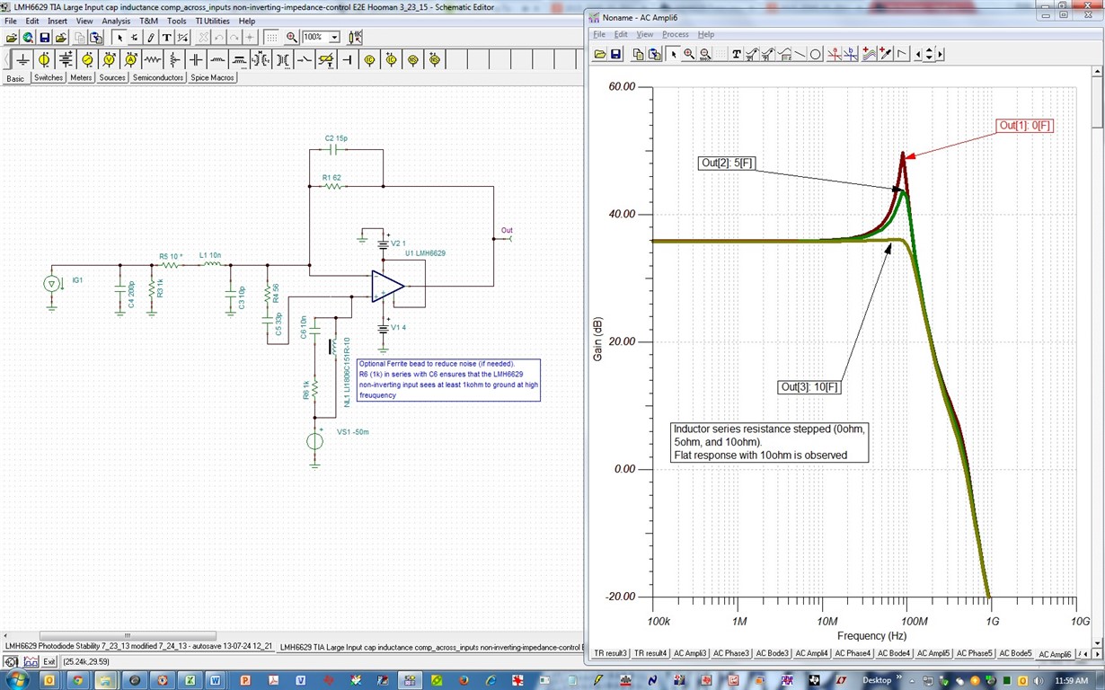
    Non-inverting input high-frequency impedance to ground:

    I noted before that this solved my instability when I had a long distance to my photodiode before. The non-inverting high frequency impedance to ground's effect on stability is not predicted / modeled by TINA-TI. Even if you are applying -50mV, the arrangement below is what I'm proposing (and which can only be verified on your setup / bench). The ferrite bead is optional only to reduce noise, if needed (you could test without it at first), but if you need to apply the -50mV bias, then it is required. I recommend you run some tests to see if the non-inverting input biasing scheme below helps or not? The -50mV biasing has little effect on the operation and may be disregarded for the time being if you do not have the ferrite bead handy. Also, please make sure that your -50mV bias source is decoupled to ground (using short lead caps) very close to where you are applying it to the non-inverting input. I would eliminate this biasing and use the R6+C6 to ground at first:

    TINa-TI file:

    /cfs-file/__key/communityserver-discussions-components-files/14/6011.LMH6629-TIA-Large-Input-cap-inductance-comp_5F00_across_5F00_inputs-non_2D00_inverting_2D00_impedance_2D00_control-E2E-Hooman-3_5F00_23_5F00_15.TSC

    Regards,

    Hooman

  • Ken,
    If you like to use R6 + C6 as I showed earlier and you don't have the ferrite bead for now, I meant to say you can replace it with a resistor (say 10kohm) to provide the DC biasing (but the noise won't be the lowest because of the noise added by this resistor). However you can see if this has any effect on instability or not?

    Regards,
    Hooman
  • Hi Hooman,
    The 50 mA is actually -50 mA. The LMH6629's output would therefore be +50 mA x 62 Ohms = 3.1 volts. The positive rail (chosen for that reason) is 4.0 volts. Also, the detector bias current changes and is not a constant 50 mA, so if I were to set the bias level on the PCB (via a pot) for the detector to -50 mV, it would change if I had a 10 Ohm resistance in series with the cable and I'm told that the detector capacitance is very sensitive to the bias. I substituted a ferrite bead for the 10 Ohm resistance in the simulation and got good results (Ferrite bead, Digikey part number 490-5176-2-ND). The peaking below 100 MHz was reduced by the ferrite. So, it looks like the ferrite, although not as good as a 10 Ohm resistor, may be a suitable option. I will try your suggestion for the non-inverting pin of the op-amp for further stability enhancements.

    ken
  • Hi Hooman,


    I would like to redesign the tranismpedance amplifier and use the unity-gain stable THS4211 instead of the LMH6629.  I'd like to lay the board out for the SO-8 package simply because if the THS4211 doesn't work, there are several single op-amps in an SO-8 package that I can use if I have too.  My question is:  I will dissipate 250 mW in the THS4211 because I will now operate it with +/-5 volt rails and it needs to sink 50 mA.  Will I have a problem with the SO-8 package since it is very difficult to heat sink it?

    Ken

  • Hi Ken,
    Please keep in mind that the THS4211 quiescent supply current is as high as 24mA (=10V * 24mA= 240mW). So, you would need to add the load-related dissipation to this value. Assuming the output voltage is at ground (0V) when you are sinking 50mA from your load, then P_load = 5V * 50mA = 250mW making the total power dissipation to be 490mW.

    The THS4211's 8pin SOIC (D- package) Theta-JA is 97.5 deg. C/W. So, with 490mW total power dissipation, the junction temperature will rise by 48 deg. C from ambient. To keep the junction below 125 deg. C, you'd then have to limit operation to 77 deg. C or lower.

    Regards,
    Hooman
  • Hi,

    I respun the board, replacing the LMH6629 with a unity gain stable THS4271.  I started testing the new board and can not see oscillation.  I do see another unexpected issue though and wonder if you could help me with this.  The THS4271 op-amp on my board does not come up correctly if the negative supply to the THS4271 comes up before the positive supply.  I say the op-amp "does not come up correctly" because I see the voltage at the "+" signal input pin at -0.8 volts whereas when it is operating properly the voltage should be -50 mV (I designed the board such that a a -50 mV bias is applied to that pin to bias a photodector connected to the - pin through the virtual ground action of the op-amp).  I use an Agilent E3631A triple supply and I can see the plus and minus supplies from the Agilent coming up at different times relative to each other , sometimes the minus supply comes up 3 ms before the positive, most of the time the negative supply comes up about 1 ms after the positive.  This is with the supply cables not attached to the board, so the Agilent is doing this itself.
     

  • Hello Kenneth,
    I can work with you to understand the power supply sequencing issue you are experiencing with the THS4271. I will try and reproduce this on the bench today. I will start using it as a standard non-inverting amplifier. Can you please send me a schematic of the circuit you are using and how you generate the 50mV bias offset on the non-inverting pin. Just to confirm, you are using the SO-8 package, correct?
    -Samir
  • Hi Samir,

    I am using the DGN package.

    Ken
  • I was a little premature in saying that the oscillation is gone. I had been working with Hooman on this transimpedance amplifer problem and he had some great advice, please see all the posts in this thread. Basically I was seeing oscillation when I used the LMH6629 high speed op-amp (stable at G=4, GBP close to 1 GHz) . I re-layed board out to use a unity gain stable THS4271 op-amp(400 MHz GBP) but I still see oscillation, at about 350 MHz. This is out of my bandwidth of interest, however, when I bandwidth-limit the scope to 20 MHz (which is at the upper limit of my bandwidth of interest) I see noise. Very frustrating. I would like to try the THS4081 (175 MHz GBP) or even the THS4051 (70 MHz GBP) simply because they are not as fast as the LMH6629 and THS4271. Consolation, condolences or any helpful comments are welcome.... please.
  • Hello Ken,
    Please send me the exact circuit schematic you are using on the THS4271, along with the expected capacitance from the photodiode. If you can also send me a photograph of the board along with an image of the layout I can look to see if there are any extra parasitics from the board that can be pushing the amplifier into oscillation. TIA circuits can be tricky to stabilize, however with a unity gain stable amplifier like the THS4271, we should be able to get things to behave well.
    -Samir