This thread has been locked.

If you have a related question, please click the "Ask a related question" button in the top right corner. The newly created question will be automatically linked to this question.

OPA698 between in-amp & ADC

Other Parts Discussed in Thread: OPA698, INA128, ADS1251, TINA-TI

Hello,

I have some trouble to use my OPA698 (voltage limiting amplifier) without gain

my actual circuit: An INA128 (in-amp) is connected to an ADS1251 (ADC). To protect my ADC, I want to limit ADC's input voltage between -0.2V and 4.5V.

the circuit I want: I would like to insert my OPA698 between in-amp and ADC. I would like to use my OPA as a unity gain buffer (G=1)

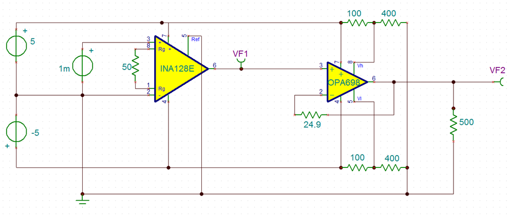
My problem: I measure the output voltage of the in-amp (OPA698 is not connected), it's stable. As soon as I connect my OPA698, the voltage value changes and starts to become instable. A 24.9 Ohm resistor is present between inverting input and output.

I suspect impedance problem, but I don't know how to solve it. More than a circuit I can implement, I'm searching the knowledge to solve this type of problem.

Help will be really appreciated.


Regards,

Julien


  • Maybe a schematic could help to understand my problem... When I try to implement this circuit on a breadboard, VF1 is OK before I connect OPA698. When I connect it, VF1 changes and becomes instable. (problem is on breadboard, it seems to work well on simulation)

    On the breadboard, I tried to add a 1k resistor (series) between INA128 and OPA698. It seems to solve the problems (VF1 value is close to the VF1value without OPA698 and is stable). But the problem comes back when I add the ADC on the OPA698's output. Otherwise, it's not a serious work to add a resistor without calculating anything... so I don't like this (bad...)solution

    So I suspect I have to add resistors, but I don't know how to calculate R values, and where to place it... My idea now is to measure INA128 output impedance, ADC input impedance, and try to add resistors to have same impedance at both OPA698's input. Could it be a good way to start ?

  • Hello Julien,

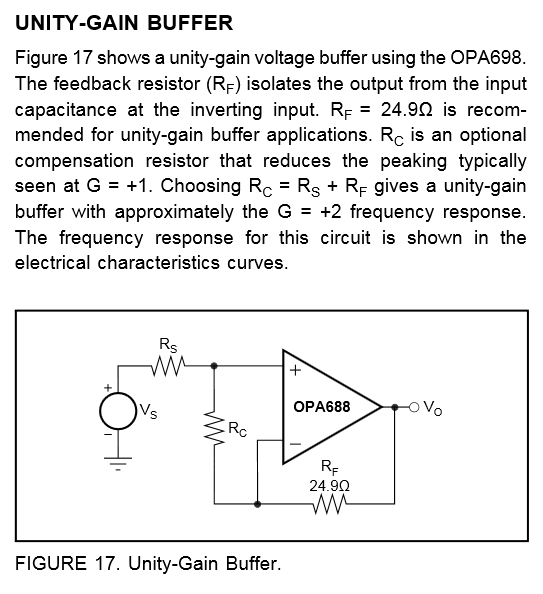
     If you look at the 1st figure on Page 7 of the datasheet, (Noninverting Small Signal freq Response), you will see that with G=+1, RF=25 and Rc=Inf, there is close to 6dB of peaking.This much peaking can lead to to an unstable system. 3dB is the most you can go to before you start to see ugliness in the time-domain and frequency-domain characteristics. If you look at the G=+1, Rs=25Ohm and Rc=175Ohm response it is much improved. Can you please add that resistance and see if you response improves?

    Additionally, I should mention that bread-boarding a high speed amplifier can lead to instabilities because of the increased parasitics. We always recommend doing the design on a custom PCB for optimum performance.

    -Samir

  • Hello Samir,
    thanks for your reply ! Your suggestion (Rc=175 Ohms) improves the response, there are no perturbations anymore when I connect the INA128 to the OPA698. It works well. Unfortunately, when I connect the OPA698 to my ADC (ADS1251), the systems becomes unstable again... For example, I measure 1.824V at the INA128's and OPA698's outputs; when I add the ADS1251, the same voltages oscillate between 1.3 and 1.6V.
    So, do you have any suggestion ?

    For the breadboard/custom PCB, I will follow your recommandations, but I have an additionnal question about this: Is it OK to test only functionnality (Just to be sure that no component is missing, not measuring performance) of an entire acquisition card on a breadboard ? Or is it necessary to test functionnality on a custom PCB ?
    I'm not experienced in analog design, so I will learn with Ti's web lesson, but the forum is really helpfull for this type of particular question.

    regards
    Julien
  • Hello Julien,

      You could use TINA-TI to simulate the amplifier along with the expected loading from the ADS1251 and the parasitics from your PCB to see if you have a potantial stability issue.

    With regards to testing functionality, I think when using general purpose catalog amplifiers you are okay breadboarding, however when it comes to high speed amplifiers, becuase of the sensitivity to parasitics it is possible to run into oscillation issues that you would otherwise not see when using a custom PCB or the EVM for the device. Are you using through-hole components on your breadboard. These tend to have much higher parasitics than surface mount components which make stabilizing the circuit a more difficult challenge.

    One thing to try is to substitude your ADC with a  500Ohm-1KOhm load and see if the output is still unstable. Dont change the wiring on your board between the ADC and OPA698. This way you can retain all the board/trace parasitics and isolate the issue (ADC or board parasitic). Please also be cautious and use a low capacitance scope probe as the impedance of the probe can also cause instability. If needed you can attach a through-hole 100Ohm resistor on your scope-tip to isolate the probe parasitics from the output of the amplifier.

    Below is a link to purchase an unpopulated EVM of the OPA698 to conduct further testing. It is fairly inexpensive and general purpose, so you could use it on future projects with amplifiers with similar pin-outs.

    http://www.ti.com/tool/dem-opa-so-1a

    -Samir

  • Hello Samir,

    I will use all your recommandations to continue my project, and buy an evaluation module to study the OPA698.

    Your help is really appreciated and usefull, so thank you and have a nice day !

    Julien