This thread has been locked.

If you have a related question, please click the "Ask a related question" button in the top right corner. The newly created question will be automatically linked to this question.

THS4052 has back to back diode inside?

Other Parts Discussed in Thread: THS4052, OPA2312

Hello

My customer intends to use THS4052 for peak detector.

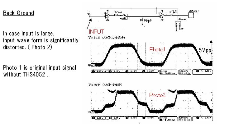
Anyway , if the input signal is large, the input signal has distortion.... attached Fig1

In case amp were OPA2312, it works well .

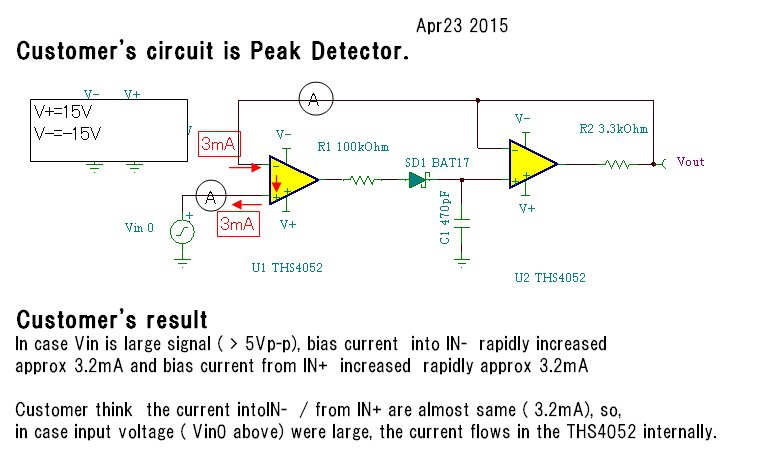
We( customer and I ) had two questions  and I  attached  the schematic Fig 2

      
(Q1)      

Please adivse the root cause of this phenomenon::  looks like large ( 3mA) bias current flowsinto in- pin

and from the  in+ pin , in case input signal is large.    

I think this is due to the limitation of Differential input voltage +/- 4V described in the THS4052 D/S page 2.  

But I could not find the current path from IN- to IN+ in the THS4052 D/S page14   simplified schematic.      

How do you think about this?       

(Q2)      
Do you think the current  flows intenally?      Is there back to back diode inside in the THS4052?      


At least, We want to know THS4052 had back to back diode inside or not.

Best Regards 


  • Hello Kanji-san,

    Very interesting problem. First off, we tried locating the design database for this part and were unable to do so because this process/part is around 16 years old. I then tried to do some further analysis and cannot seem to wrap my head around how we could have multiple back to back diode AND the 3.3KOhm resistor and still get 3.2mA of current. 3.2mA*3.3K will give around 10V of drop. However you mentioned only a 5Vpp signal so this doesnt seem to make sense. The diode would add further voltage drops and make this scenario (3.2mA) even harder to imagine.

    Because of the +/-4V VIO max. spec I dont believe there are any diodes at all. Can you please tell me what the frequency of the input is (isnt very clear in the graph).

    A simple way to determine the amount of current flowing is to put probes on either side of the 3.3KOhm resistor and check the differential voltage across it. Has this been done?

    -Samir

  • Dear Samir san.
    Thank you for your answer quickly. Please allow me send another POST in order to attach the waveform.
    Thanks and with my best regards