This thread has been locked.

If you have a related question, please click the "Ask a related question" button in the top right corner. The newly created question will be automatically linked to this question.

OPA 2356 parameter "Voltage Output Swing from Rail"

Other Parts Discussed in Thread: OPA2356

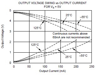
I'm a test engineer and we are testing OPA2356 for a customer and are consistently failing the "Voltage Output Swing from Rail" parameter based on the values reported in the datahseet at 25C. The upper limit specified for the max voltage swing from the supply rail is 1V. However, despite our best efforts, we are consistently seeing a value approximately 35 to 40 mV greater than 1V for the max output swing from the negative rail (-2.5V) for opamp A (Note: we have configured the power rails for mid supply at -2.5V and +2.5V). In the same datasheet, there is a graph of Output Voltage versus Output Current at various temperatures. For the curve at 25C, the max allowed voltage swing from the negative rail at 100 mA appears to be much closer to 1V than the max allowed voltage swing from the positive rail at the same current and temperature--being less than 1V by a greater amount. Does the limit value for the output voltage swing stated in the datasheet apply only to the positive rail (+2.5V) at 100 mA or is it equally applicable to the negative rail (-2.5V) despite the narrower margin illustrated in the graph? The graph also states "Continuous current above 60mA are not recommended" but the max output voltage swing parameter is specified at Io=100 mA. Should that particular parameter value be measure only under pulsed current conditions (<300 us)? Does the graph of output voltage swing versus current for Vs=5V support the max 1V limits specified earlier in the datasheet? Any help you could offer would be greatly appreciated. Thanks.

  • Hello John,

    The limit value for the output voltage swing stated in the datasheet apply to both the positive (+2.5V) and negative (-2.5V) supply rails at 100mA, and can be maximum of 1V from each rail. Yes, even though the part can support the maximum output current of +/-100mA, the continuous output current should be limited to within +/-60mA and momentary output current drive of +/-100mA like the pulse current conditions are okay. The graph of output voltage swing versus current for Vs = 5V provide the typical and not the worst case response across temperature.

    Would it be possible to know what load and output swing is being targeted at the output of the device? Also, a schematic would definitely help to debug further.

    Best Regards,

    Rohit

  • Thanks for your reply. The load current we are using is 100 mA pulsed for about 500 us. You mentioned that the graph at 25C and 100 mA is typical. In that case, would it not be true to say that the device measures very close to the 1V limit and would occasionally but infrequently equal or slightly exceed that limit? I'll work getting you a schematic of the test circuit if that would help.

  • Hi John,

    Yes, in the 100mA pulsed scenario, which I don't think I would recommend, the device measures very close to the 1V limit and could occasionally be slightly exceeding the limit. The output current that the OPA2356 can source/sink also depends upon the ambient temperature of the part. As you can see in the below graph, if the device sits at slightly higher temperature than 25'C, which it could due to board heat-up, you will be missing the target of 1V limit with a +/-100mA output current. The 35-40mV is also a small number and it would depend upon the scope or sense resistor accuracy that you have in your system. May I know are you measuring the output on a scope or measuring it on an ADC?

    Yes, a schematic of the test circuit would definitely help.

    Best Regards,

    Rohit