This thread has been locked.

If you have a related question, please click the "Ask a related question" button in the top right corner. The newly created question will be automatically linked to this question.

Question on differential amp like LMH6552

Other Parts Discussed in Thread: LMH6552, TINA-TI

Hi

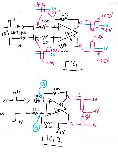
I have question with the differential circuit above with gain of 400/200=2.  In both cases, I have a differential input pulse base line at 0V and 1V amplitude as shown. The duty cycle of the pulse is 10%( say peak for 5nS and back to 0V for 45nS).


In Fig.1, I have AC blocking cap on both inputs. The Vcm is tied to ground so the common mode output voltage should be 0. BUT, if you look at the other side of the two capacitors, because of the 10% duty cycle, the base line of the input pulses are SHIFTED as shown. The base line of the +ve pulse has shifted to -0.1V and -ve pulse to +0.1V as shown due to the 10% duty cycle. This actually becomes differential mode voltage and CANNOT be eliminated. The base line of  -ve output is at +0.2V and +ve output is at -0.2V as shown. So if I DC coupled to the next differential stage, the baseline will follow. This means I created an offset due to duty cycle of the input. Am I correct?

In Fig.2 I do DC coupled, but notice the Vcm=+1V. So the baseline of both outputs is 0V no matter what. If you look at the input side, it is driven by differential pulse with baseline at 0V. What will the base line voltage at point (A) and  (B) in BLUE? Is it simple division and is +0.333V on both input of the differential amp?

Do you have any application notes to explain at these basic circuits for differential amps? Can you give me the link?

Thanks

Alan

  • Hi Alan,

    What you are measuring with the LMH6552 two situations (AC coupled, and DC coupled) seems reasonable to me.

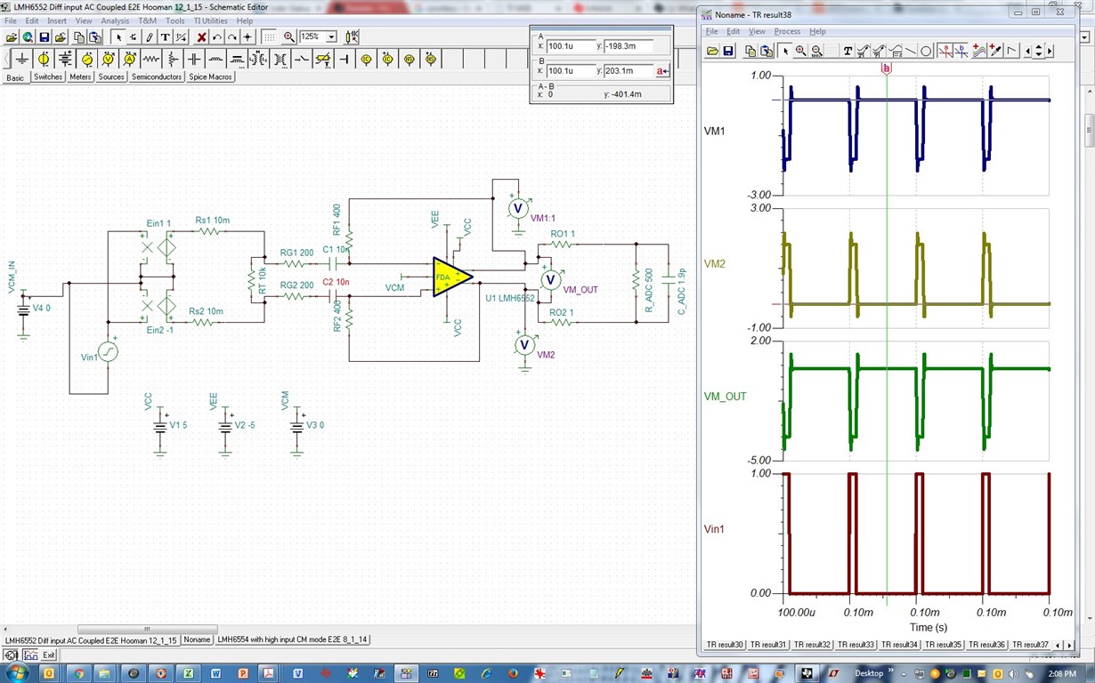
    For the AC coupled case (Figure 1), remember that there can be no average current flow through the AC coupling cap (as with any capacitor). So, the average current through the feedback resistor is also 0mA. Therefore, with 10% duty cycle, the output waveform will settle to an average voltage of 0V when VCM= 0V (i.e. +1.8V and -0.2V on the positive output with 10% duty cycle).

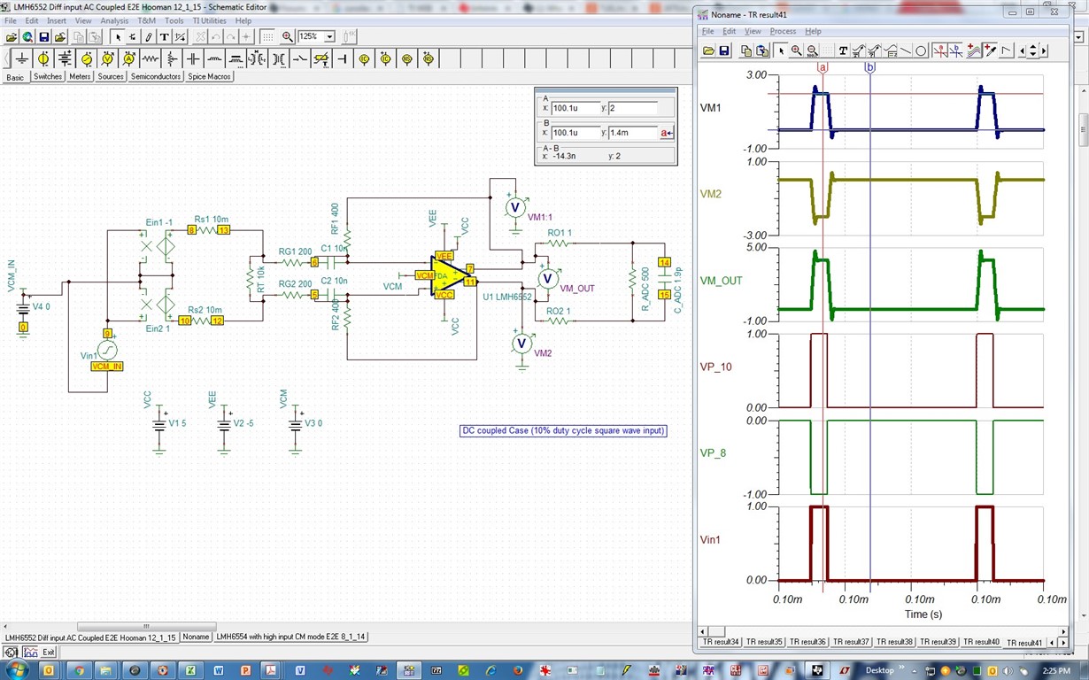
    When DC coupled (Figure 2), there is average current flow through the 200ohm input resistors. So, when the positive input jumps to 1V, 5mA of current flows (=1V / 200ohm), which then produces an inverting output voltage of -2V (= 5mA * 400ohm). The corollary of this occurs on the inverting input and the non-inverting output. This case does not dictate anything on the output average waveform. The only thing dictated is that when 0V input, both outputs have to be at 0V (VCM=0V).

    The TINA-TI simulation also agrees with your measured results. Here is an image and a file you can use for your waveform:

    LMH6552 Diff input AC Coupled E2E Hooman 12_1_15.TSC

    Regards,

    Hooman

  • Hi Alan,

    I forgot to mention that the DC coupled case (Figure 2) waveform you've drawn does not seem right! TINA-TI simulation shows that the output waveforms swing between 0 and 2V (and between -2V and 0V on the other output pin), while you show each output swing from -1V to +1V:

    LMH6552 Diff input DC Coupled E2E Hooman 12_1_15.TSC

    Please double check your Figure 2 waveform and let me know.

    Regards,

    Hooman

  • Hi Hooman

    Thanks for the response, I understand the average voltage is 0 if Vcm=0. I am referring to the base line, they should be +/-0.1V to get average of 0V.

    Thanks

    Alan

  • Hi Alan,
    I'm not sure I understand your question. Please rephrase if you can.

    Regards,
    Hooman