This thread has been locked.

If you have a related question, please click the "Ask a related question" button in the top right corner. The newly created question will be automatically linked to this question.

Help with building a AC amplification circuit with DC offset, using LM7171 opamps

Other Parts Discussed in Thread: LM7171

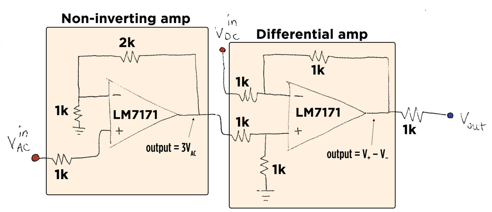
Hello! I am trying to build a circuit that has 2 steps:

it first amplifies an AC voltage (up to ~5 kHz only) from a function generator (non-inverting amp)
2) the amplified AC signal then undergoes a DC shift (differential amp)

The problems:
  - the final gain for the AC signal seems to be only 2.75, not 3.
  - the output of the differential amp is behaving as the following equation: V_AC + 10 - V_DC.

For example, if V_AC = 1*sin(wt), then the output with V_DC = 0 would be 10 + 2.75*sin (wt)
If V_AC is 1*sin(wt), and we use V_DC = 10V, then the output = 2.75sin(wt)

Any suggestions as to why these behaviors are occurring?

Many thanks,

Aaron

 1)

  • Hi Aaron,

    I cannot pinpoint something obvious.  Here are some comments / suggestions anyways:

    1. Make sure the LM7171 has a total supply voltage (Vcc - Vee) of at least 5.5V (e.g. +/-3V or higher). Total supply should also be less than 36V for this part.

    2. The LM7171 input requires headroom to both Vcc and Vee. So, you must use dual supplies (e.g. +/-3V or higher). Single 10V supply (or similar) would not work with this part due to the headroom requirement.

    3. At the "AC in" port, if you use a bench generator, I suggest you use a 50ohm shunt to ground to ensure the coax cable carrying that signal to your board is properly grounded. Also, only then would you get the proper amplitude that your generator states (e.g. if you set your GEN to 1Vpp, with 50ohm termination you'd get that swing. You'd get double the swing if you do not terminate as you've shown your input).

    4. At the port where you bring in "Vdc" to the board, make sure you decouple that point to ground using a shunt capacitor (e.g. 0.1uF) to make sure any lead inductance on that pin is not causing instability.

    5. Make sure your LM7171 packages have local / short lead supply decoupling caps to ground on your board and that you use ground plane on your board to keep ground inductances low (LM7171 is a 200MHz part and even though your signal is only 5kHz, you should apply high frequency layout techniques).

    6. Probe the device(s) input and output pins for voltages and make sure there is at least 2V of headroom from these to either V+ or V-.

    7. Make sure any scope lead that you are using is not causing instability due to its capacitance.

    8. Monitor the supply currents you are pulling and make sure you are not seeing excess supply current (which could be indicative of an oscillation).

    Regards,

    Hooman