This thread has been locked.

If you have a related question, please click the "Ask a related question" button in the top right corner. The newly created question will be automatically linked to this question.

High speed operational amplifier

Other Parts Discussed in Thread: LM7171, TLE2142, CSD18542KCS, THS3091, THS3061, TLE2141

Hi,

I am looking for a high speed operational amplifier, with supply voltage range +15 to -15 or specifically 0-15 V should be fine.

My application is to maintain the value at the inverting terminal equal to that at non inverting terminal. To develop voltage at inverting terminal equal to that at non inverting terminal, output should go high that would be given to the gate of a mosfet, which then would allow some current flow through the mosfet. The inverting terminal would be connected across a current sense resistor, through which this current is expected to sink. So, ideally whatever voltage is there on non inverting terminal is expected to appear across this current sense resistor.

This application is a constant current load.

Also, the slew rate of the opamp should be high enough.

One op-amp that I could figure out is LM7171, but its slew rate depends on differential input voltage.

TLE2142 is yet an another opamp, but has less slew rate.

Look forward to get suggestion for some suitable part.

Thanks.

  • Hello Salil,

    Can you please confirm if you are trying to use a circuit similar to this one, except with a MOSFET? Also, can you please let me know what the slew-rate required is? or...how much current are you trying to pulse at what edge rate?

  • Hey Samir,

    Thanks to reply.

    Yes, this is the exact circuit (Constant current load) I am building for my VRs to be tested for fast rising transients. And the mosfet is also used in my circuit.

    Below is the circuit that I had simulated using TINA with some arbitrary opamp, output of whose is given to the gate of CSD18542KCS Mosfet from TI.

    I expect the opamp to work as error amplifier for this circuit, and with high slew rate so that current through the mosfet could sink at high slew rates.

    Maximum of 0.15 V or 150mv ranging from 0V is required to be given at the non inverting terminal of the op-amp, so that I can get 0.15V across 5mohm Rsense and hence I should be able to sink (0.15V/5mohm=30A) current, in form of square wave(0-30A).

    Please suggest an op-amp to be used for this application with minimum offset voltage, maximum slew rate possible, with more than 15V supply (so that output can go atleast 13V)

    Regards,

    Salil 

  • Salil,

    I think you will need to first narrow down on which JFET/CMOS transistor you are going to use in your application. Once you know that you may find that with a Vgs of say 4V you can supply your required current....(this is just a number I threw out, I am not really sure how much Vgs is actually needed). You will need to find the Vgs_Ids curves of the JFET to determine this, you may even need to parallel multiple transistors to achieve this.

    Also, if you are looking to do a high side current source here is a more appropriate reference design for that:

    -Samir

  • Sali,
    BTW the THS3061 and THS3091 both have slew-rates of 700V/us and can operate on +/-15V supplies. It does look like you really aren't using the negative side of the supplies. Is that correct? We can skew the supplies to say +25V/-5V in case you need more swing for any reason.
    -Samir
  • Hi Samir,

    THS 3061 and 3091 are current feedback amplifiers. And I am really not sure how they would behave in the circuit that I have described. On reading about current feedback amplifiers, it says that these require compensation as compared with voltage feedback amplifiers.

    In TINa, yes they are behaving exactly as per the application requirement, but I really dont know how they would act otherwise.

    And yes, I have no use of negative supply.  On running LM7171 in TINA, it looked that the slew rate was less when negative supply was not there and so I decided to use negative supply. But in application, there's no requirement for that.

    Plz let me know about this, if you could figure out some op-amp suiting my requirements.

    Thanks Samir.

  • Hi Samir,

    It would be really great if you could confirm how THS3091 would behave in my circuit. In TINA, it gives great results.

    Thanks

  • Salil,
    The TINA simulations will give you a very good idea of system performance. I too would rely on the TINA simulations to evaluate the performance prior to designing the boards.
    -Samir
  • Great Then Samir,

    I have ordered some samples for THS3091. Lets see how it would behave in my circuit.

    I will share the results with you.

    Also, I need to figure out some other things and it would be really great if you could just have a look at it.

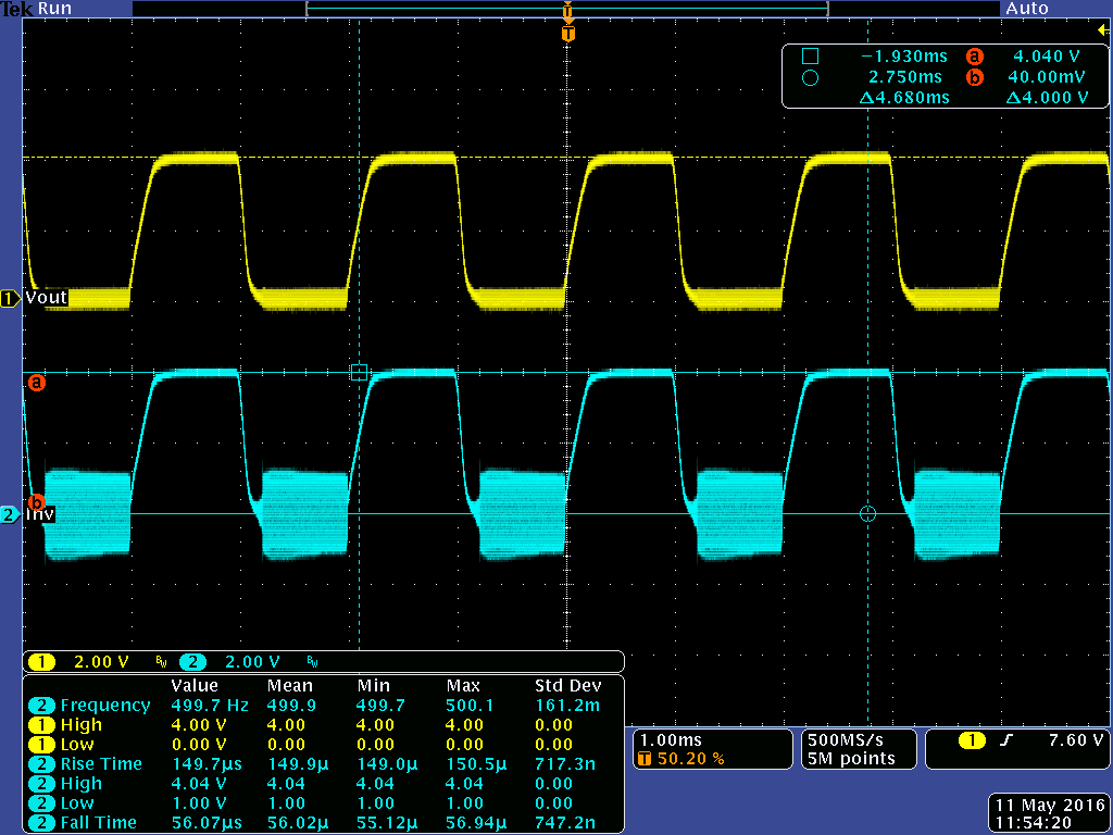
    The test board that I made now has a 1ohm resistor, just to see the performance of yet an another op-amp, TLE2141. So ideally whatever voltage is given to the non inverting input should appear across this 1 ohm resistor to draw same amount of current from the load provided voltage of the source is more than that at non inverting terminal.

    I am getting some results that go with the simulations (except the slew rates), but I am able to see some ringing in the circuit.

    Can you just have a look and suggest any changes.

    So, the yellow waveform is voltage given at the non inverting input of TLE2141. It seems inverting terminal voltage follow the volt at n.inv terminal, however if you could see there is some ringing of frequency 5Mhz, when the voltage goes to 0.

    If possible, can you explain the reason for this.

    Regards,

    Salil

  • Have you tried this out in TINA yet? I would do that first and check the phase margin. Also, for some reason the yellow waveform also looks noisier on the bottom level vs. the top level.